This thread has been locked.

If you have a related question, please click the "Ask a related question" button in the top right corner. The newly created question will be automatically linked to this question.

TIDA-010042: MSP430F5132 PWM SIGNAL TD0 AND TD1 WIDTH IS VARYING FOR THE SAME DUTY CYCLE VALUE

Part Number: TIDA-010042
Other Parts Discussed in Thread: MSP430F5132

Tool/software:

Hi,

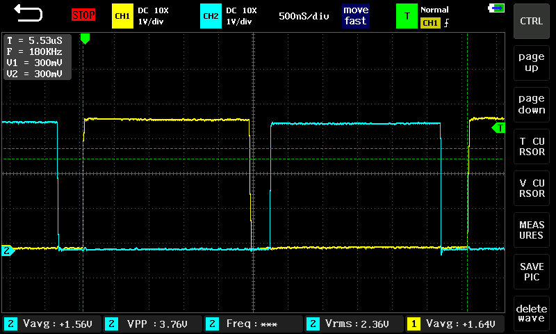
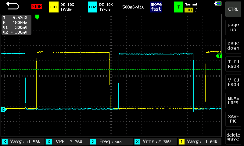
When I checked pwm signal of high side gate signal of two phases(TD0 &TD1), width of one phase is more than the other. For verification when I checked by forcing a fixed duty cylce value for both TD0 and TD1, same issue I observed(ie, width of pwm is different).I have attached the waveforms.Yellow waveform is TD1 and blue is TD0

 Is there any issue for msp430f5132 for pwm generation.

TD1-HIGH SIDE GATE SIGNAL(ON TIME)-YELLOW.bmpTD1-HIGH SIDE GATE SIGNAL(TIME PERIOD)-YELLOW.bmpTD0-HIGH SIDE GATE SIGNAL(ON TIME)-BLUE.bmpTD0-HIGH SIDE GATE SIGNAL(TIME PERIOD)-BLUE.bmp

  • Hi Cyril,

    Sorry for the late reply, i just came back from holiday.

    It seems in the waveform, the channel2 signal, you ended at level '0'. While in the channel1 signal, the cursor ended at level '1'.

    The fall edge of the signal also takes some time. Please check the fall and rise time of the signal.

    And do you set the same dead time for the 2 channels?

    Thanks & Regards,

    Bowen