A related question is a question created from another question. When the related question is created, it will be automatically linked to the original question.
If you have a related question, please click the "Ask a related question" button in the top right corner. The newly created question will be automatically linked to this question.
WEBENCH-POWER-DESIGNER: Webench Power design simulator
Webench is a browser based tool. We cannot share this as an standalone application. Most of our devices provide simulation models for different tools like PSpice and Simplis on their product page.
Can you provide more information on which device you need support on?
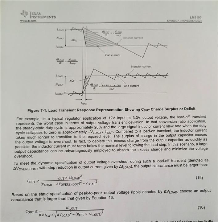
Could you help me the cout formula where Iload step increase and voltage overshoot is needed ., how to calculate Iload step increase and in attached picture Lout is it inductor value or inductor current
1. Since the device is a controller, there is no theoretical output current limit. But it is recommended to limit the output current less than 20A (or >2mΩ sense resistor) because it is practically not easy to keep the signal-to-noise ratio if using less than 2mΩ sense resistor.
2. It is not specified in the datasheet, but typically ~3mA (Please refer the MOSFET driver power consumption in the section 9.1.2.4 of https://www.ti.com/lit/ds/symlink/lm5146.pdf )
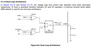
3. Please refer the section 6.3.14 in the datasheet. It is not allowed for me to disclose more details inside the IMIN selector.
4. MOSFET driver is sourced from VCC regulator. The regulation target of the VCC regulator is from 7.125V to 7.875V
I will be out of office and I will not be able to reply this E2E post anymore. If you are still trying to resolve the issue, please don't reply on this post, but create a NEW post to get a help from other engineers quickly. -EL