This thread has been locked.

If you have a related question, please click the "Ask a related question" button in the top right corner. The newly created question will be automatically linked to this question.

UCC28950: The PSFB design based on UCC28950 has no phase shift

Part Number: UCC28950
Other Parts Discussed in Thread: UCC27714

Tool/software:

Currently, we are facing a problem with the PSFB design based on UCC28950. The design is 240W, 48Vout, 5A Iout, 700Vin, Fsw 100KHz. In addition, the Tx turn ratio is 12.4:1. 

--------Q1------Q3          Q5---------|--Vout+

           |            |   TX     -------L---|---Vout-

--------Q2------Q4          Q6---------|
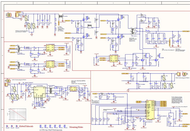
The problem is, in the light load situation, we can get 48Vout. But there is no phase shift for the Vds (Q3, and Q4), so there is no deadband on the Tx waveform. Ideally, when I give 700Vin, based on the turn ratio of the Tx, I can get 53V without control. If I get 48V, the TX waveform should have a deadband, but it is not. After that, I add load, the Vout starts to drop.

So, can you please help us, with why there is no phase shift?  

Please see the waveform attached.

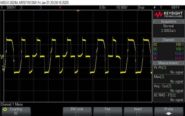
The picture below is the Tx waveform, which is damping when the load is only 200mA. When the load is above 200mA, the waveform will become an “H-bridge” with 50% duty cycle.
The picture below is the Vds of Q1 and Q4. Yellow is Q1, Green is Q4. This is still on the 200mA load situation. You see the phase shift angle (direction) of Q4 is wrong.
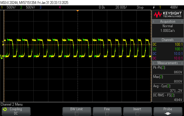
 

I am very confused why no phase shift (or the wrong phase shift happening). Is that because of Tx or IC set up? Or Tx turn ratio not correct.

  • Hello,


    I reviewed your schematic and it does not look like you are driving your H Bridge correctly with gate drivers.  Your H Bridge drivers on the high side FETs are ground reference and will not be able to drive the FETs.  To turn on the FET the driver needs to drive the high side FETs gates at Vin + Vgs(th).    I think a good part of the problem is that you are not driving the H Bridge correctly.


    You can use two half bridge drivers to drive the half bridge.  The following link will bring you to design using two UCC27714 half bridge drivers to drive the H Bridge.  You can see the configuration that you need to use in figure 1.

    https://www.ti.com/lit/ug/sluub02a/sluub02a.pdf

    https://www.ti.com/lit/ds/symlink/ucc27714.pdf


    Once you resolve driving the H Bridge the following link will bring you to an application note showing the step by step design process of a PSFB using the UCC28950.  It goes through the step by step design process and you can use it to check your design.  There is even a link to an excel file in the application note that you can use to check the design.  It uses the same equations that the application note uses.

    https://www.ti.com/lit/pdf/slua560


    If you have any questions on how setup the UCC27714 H bridge driver please repost in the e2e with the UCC27714 in the thread title so the appropriate applications engineer can answer your questions.


    Thank you for interest in Texas Instruments (TI) products.  If you have a related question, please click the "Ask a related question" button in the top right corner. The newly created question will be automatically linked to this question.


    Regards,