This thread has been locked.

If you have a related question, please click the "Ask a related question" button in the top right corner. The newly created question will be automatically linked to this question.

TIDA-050047: Updated for TPS25751S Bus Controller with BQ25792 Charger IC

Part Number: TIDA-050047
Other Parts Discussed in Thread: BQ25792, BQ24617, BQ25792EVM

Tool/software:

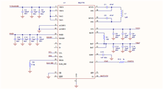
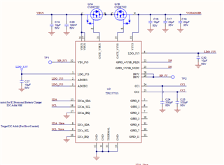
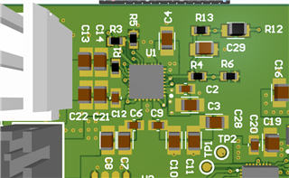
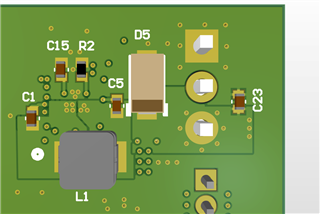
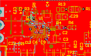
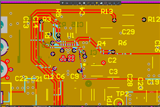
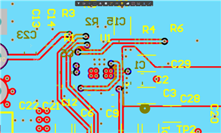
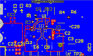
I'm implementing the TIDA050047 design using the TPS25751S Bus controller with the BQ25792 Charger IC for a 4S2P battery charger system.  I've set the firmware up for the following parameters:

Configuration: TPS25751S Sink Only with BQ
Maximum Power Sourced: Disabled
Maximum Power Sinked: 45W
Preferred Role: Disabled (Power Sink)
USB Highest Speed: No USB Data
Preferred Data Role: Disabled
Suport BC 1.2: NO
Support Liquid Detection: NO
Vendor ID USB-IF: Use TI's
Product ID: Use 0x0000
Charger to Integrate: BQ25792 (series)
Percentage Above PD Contract Current: 10%
Percentage Below PD Contract Voltage: 10%
Battery Charging Voltage 16.4V
Battery Charging Current: 2A
Charger Termination current: 120mA
Precharge Current: 120mA
Dead Battery Clear Threshold: Disabled

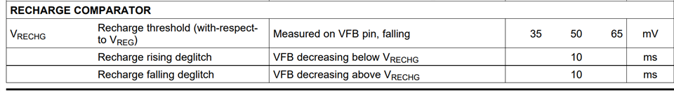
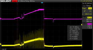
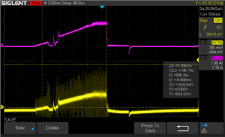
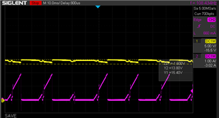
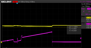
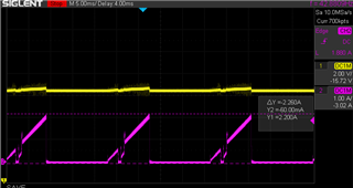
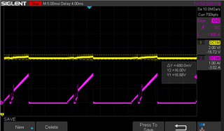
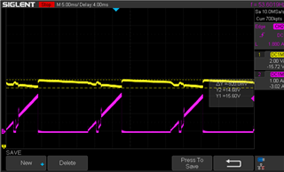
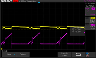
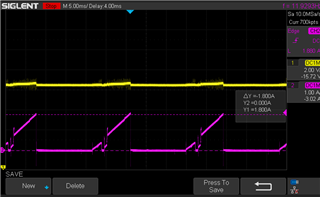
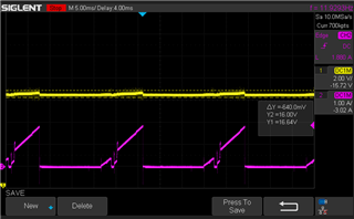
and I'm charging with a 65W PD charger that is supplying 15VDC VBUS per the protocol.  I have an odd thing happening towards the end of the charge cycle.  When the battery charge gets up to around 15.8VDC the charger starts going in and out of charge indication.  The charge current peaks to around 1.8A with indicates to me tha tit should be in the Constant Voltage charge mode on the decaying charge current curve.  When the current peaks, it is pulling the voltage at the battery connector up to 16.4VDC and seems to shut down.

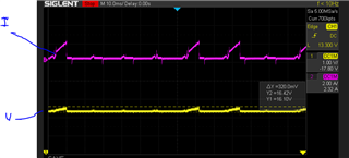
It stays doing this slowly charging the battery up until it hits around 16.2VDC as measured with a meter, then it falls back to constant voltage with the current slowly decreasing as expected and a constant indication of charging until fully charged.  I'm not sure what would be causing this.

  • Hi Michael,

    In CV mode, the charge current should be tapering down not up.   If the BAT pin is still connected to the battery cells, the current and voltage should not move as quickly as your plots show.  Is it possible that the battery pack protector is opening and closing?  

    Regards,

    Jeff

  • An interesting thought.  I have reproduced this with two different batteries, and in each case they charge with a constant 2A prior to hitting this stage.  Then they have this issue until they reach the point where the current doesn't create the voltage ripple at the battery (or at least that's my assumption as to why it stops) until it reaches the current cut off point.  Since the battery protection circuit holds at the 2A point, I'm not sure what whould cause it to be instantaneously opening and closing as to have the waveform shown.

  • Hi Michael,

    If you lower the charger to say 1.5A, do you see the same issue?  

    Regards,

    Jeff

  • Ok, so first let me give you a little history on this product.  I'm working on the third generation of it, and we have over 50K units of the previous two generation in the field all using the exact same battery pack.  The previous two generations were using a TI BQ24617 charger IC fed with a 19VDC wall wart.  Needless to say we did not see any of this previously.  That being said I dug up a previously returned battery pack that had been returned due to thermistor connection failure.  I bypassed the protection circuit and hooked it up to the same charger board I was previously using.  While I can't say whether or not the protection circuit adds to the issue, it is definitely not the sole reason.  The issue was reproduced in this configuration.  It appears that when the charger attempts to switch over from constant current, to constant voltage, the detected voltage drops causing it to drop out of charge and restart the sequence.  So I then reprogrammed the board to charge at a 1A charge current.  In that case the issue did not occure.  So it appears to me that there's an issue at the point of change over from constant current, to constant voltage output allowing the voltage to drop enough to trigger a recharge cycle.  Thoughts?

  • HI Michael,

    The change from constant current to constant voltage is not a digital switch, its an analog handoff.  Do the status/fault flags report that charge status is changing to termination then back to recharging? If not for the double pulse, the time between pulses is close to the the lowest recharge deglitch time setting in REG0x0A. Is your recharge threshold set to the default or closer to 320mV?  Did the BQ24617 charge at 2A as well or only 1A?  Could it be the battery voltage (impedance really) relaxing after charge stops, causing a voltage droop and recharge? 

    Does the same thing occur if you use the BQ25792EVM?  If you don't see the same issue with the EVM, how does your PCB layout compare to the EVM?  The SYS and PMID 0.1uF capacitor must be placed on top of the IC, connecting the PMID, SYS and GND pins without vias.  If the SYS 0.1uF cap is not placed there, the switching noise couples into the BATFET current sense amplifier, causing the amplifier to measure the wrong charge current. I am not aware of issues with the voltage on BATP that controls the CV loop but I can't explain why the charger stops charging at 16.1V.  What does the voltage on BATP pin look like?

    Regards,

    Jeff

  • Ok, first I have no means at the moment to query the I2C of the charger chip.  This is following the reference design and the programming of the charger chip is handled by the buss controller.  As far as the actual status pin, it toggles to charge complete and back again in sync with the charge current dropping to zero then restarting.  Its not indicating a fault because the period is random and again in sync with the previous waveforms shown.  The previous generations charged at 2A, though a few started out at 3A.  1A doesn't meet our customer's charge time requirement.  I haven't set up to run the two development boards together in this configuration so I can't respond to that question.  C6 (0.1uF SYS) and C9 (0.1uF PMID) are both on the top along with the charger chip..  

    The recharge threshold is the default because I see no way of adjusting it through the buss controler IC on line programming structure, though I may be missing something there.

    "Could it be the battery voltage (impedance really) relaxing after charge stops, causing a voltage droop and recharge? "  Yes that is exactly what I think it is since the lower charge current doesn't create as large a drop when it switches from costant current to constant voltage.  I'll have to look at the previous generation product and see if it had a larger recharge threshold which could account for the reason we wouldn't have seen this issue.

  • Hi Michael,

    BQ24617 recharge threshold is 50mV multiplied by the feedback divider, so 2x50mV.  Its deglitch time is shorter so I would expect BQ24617 to toggle more frequently.  

    Regards,

    Jeff

  • Actually our divider string on the previous gen product was 680K and 100K so the recharge threshold would be more like 0.39V so larger than the current design I'm working on.

  • Ok, I had the software group change the recharge threshold from its default, to 400mV, but I still see the issue so I'm back to assuming its some sort of noise issue probably caused by something in the layout.  Here are some additional scope shots I've taken while is in this oscillation/restart mode.  The top trace is current, and the bottom trace is the ripple voltage on the VBAT pin taken on C12 (100nF).  The battery charge current is set for 2A and as you can see this appears to be operating within the constant voltage phase of the charge cycle because the charge current stops at ~1.6A.

    This is the same scope shot but the cursors are on the voltage ripple.

    and here its zoomed in that shows some sort of ringing that sarts up that appears to be either the cause or an effect of the shut down.

    So we've also ran into an emissions issue on our precompliance scans so I'm currently looking at improvements to the grounding of the chip.

    Here's a top view of the current layout

    And its a 4 layer board, 2OZ copper.

    So looking at the layout, here's the changes I currently have in place

    On the top layer I modified the ground vias so I was able to get a ground flow connection from Pin 27 though to the ground connections on the opposite side of the chip.  It also allwed me to move C6 and C9 a bit closer to the chips pins on VSYS and PMID.  I also moved C29 so it is directly off of pin 5 REGEN.

    I moved a bunch of the signal traces off of layer 2 to get a more solid ground plane directly under the chip

    On the bottom layer I centered the inductor with the chip on the top of the board and allowed ground flow under the inductor flowing through under the chip.

    Any thoughts regarding what I can do on the current boards to address the odd operation, and comments on the new layout?

    Thanks,

  • HI Michael,

    The new layout follows the PMID and SYS capacitor placement recommendation so I expect IINDPM and ICHG regulation to be within spec.  The SWx pours/planes to the inductor are quite large and have ground immediately under them.  Those pours/planes and GND form a pulsing capacitor that spews EMI. 

    Your charge profile is still puzzling.  I don't understand why the charge current ramps up so slowly.  This part does not have ICHG soft start.  What do the status and fault registers in REG0x1B-0x27 report during this time and then immediately after the drop off?  The ramp implies there is a variable resistance somewhere in series between the BAT pin and pack battery cells.  I suspect the sudden drop off in voltage is due to voltage created by a fixed series resistance x ICHG being removed when the charge enters termination.

    Regards,

    Jeff 

  • Ok, I made some adjustments to the inductor copper pours like you suggested.  I've also gotten my hands on an Ardvark I2C host adapter and am now able to read registers.  I have no idea how to time the readings to be in sink with different parts of those waveforms, but here's a report on what the registers are reading out.  Note the prior point readings were during charging at the cnstant current point of 2A.  The input buss voltage was set for 15V.

    Reg 1BH: Bounces between 8FH 07H an 0FH while in this odd mode, was steady at 0FH prior

    Reg 1CH Bounces between 70H and 10H while in this odd mode.  Was steady at 70H prior

    Reg 1DH Constant at 01H during this mode and prior

    Reg 1EH Constant at 00H durinng this mode and prior

    Reg 1FH Constant at 00H durinng this mode and prior

    Reg 20H Bounces between 40H and 00H during this mode was constant 00H prior

    Reg 21H Constant at 00H durinng this mode and prior

    Reg 22H Constant at 88H during this mode, was 00H prior

    Reg 23H Constant 80H during this mode was 00H prior

    Reg 24H Constant 00H during and prior

    Reg 25H Constant 00H during and prior

    Reg 26H Bounces between 60H and 40H during was 00H prior after initial read of 40H

    Reg 27H Constant 00H during and prior

    Because of the indication of VBUS_OVP I also read out  Register 35H and read a constant 38A2H indicatign a bus voltage of 14.498V

    Here's a wide shot of the current vs VBUS voltage taken at pins 2 & 3 of the charger chip

    I zoomed in to see if there was some high frequency spike I wasn't seeing, but couldn't see anything

    I also double checked that the recharge threshold had been set to the 400mV I requested and it was.  I did set it to the max 800mV but it had no real change on the issue.

  • HI Michael,

    So you are moving between VBUS OVP, VBAT OVP and IINDPM (input current limit) and normal charging.  You could monitor/trigger by INT pin to know when a FAULT in REG0x22 to 0x27 trips.

    Can you monitor ICHG and VBAT as well as VBUS and IBUS on the same scope plot?

    Regards,

    Jeff

  • I haven't brought out the INT pin so I'll have to see if I can get a wire on it.  Also only have two channel scope so only can do two measurements at a time.

  • Ok, so not sure how I can trigger the Ardvark host adapter to poll a register when the Int fires, so ignoring that for now.  As for the measurements here's what I got:

    Here's buss current vs battery voltage.  Current measured.

    Same with battery voltage measured.

    Here's Buss current vs. Buss voltage 

    Here's charge current vs. Buss voltage 

    Charge current vs.  Battery voltage  current measured

    Charge current vs. Battery voltage

  • Hi MIchael,

    Thanks.  Unfortunately, I am still stumped.  The charge current should not ramp like that.  I can't explain it.  It you use a simulated battery, for example, a 4 qudarant power supply or power supply || eLoad set for CV, do you seem the same charge profile?

    Regards,

    Jeff