This thread has been locked.

If you have a related question, please click the "Ask a related question" button in the top right corner. The newly created question will be automatically linked to this question.

TIDA-080008: DLP & TIDA-080008 - LED Driver Calculator Tool

Part Number: TIDA-080008
Other Parts Discussed in Thread: TPS92641

Tool/software:

Hi Team,

Good day. I am posting this inquiry on behalf of the customer.

This query is regarding TI TIDA-080008 LED Driver Calculator Tool

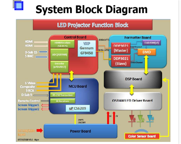
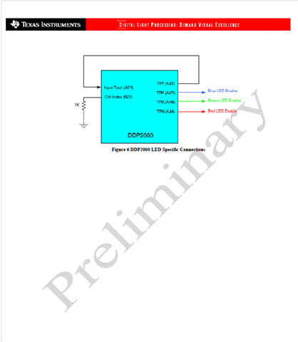
  1. I am using different LED. Can you please provide component number and value I need to use in TIDA-080008 for below LED's. Also can you please share the excel calculator. Input signal will be three ENABLE signals RGB 3.3V TTL as mentioned in attachment.

    https://www.mouser.com/datasheet/2/588/prd_pim_datasheet_8160606_EN_pdf-3419578.pdf
    https://www.mouser.com/datasheet/2/588/prd_pim_datasheet_8159967_EN_pdf-3418893.pdf
    21V/10A

    https://www.mouser.com/datasheet/2/588/prd_pim_datasheet_8158824_EN_pdf-3419535.pdf
    17.4V/8A

  2. I am not using PWM, there is only three ENABLE signals RGB (Please refer to image) simulating color wheel. Please suggest, do I need to make any change to VREF(PIN5) and IADJ(PIN6) circuitry if I am not connecting any PWM signal.

Thank you for your help.

Kind regards,

Marvin

  • Hello Marvin,

    1. We don't have a published tool. As mentioned in this thread, the customer should utilize the datasheet details to calculate for their solution.

    https://e2e.ti.com/support/power-management-group/power-management/f/power-management-forum/975436/tps92641-tida-080008-led-driver-calculator-tool

    Although, the steps to do this is seen within section 8.2.1.2:

    1. Set Output Voltage Feedback Ratio (EQ# 17)
    2. Set Switching Frequency (EQ# 18)
    3. Set Average LED Current (EQ# 19)
    4. Set Inductor Ripple Current (EQ# 20/21)
    5. Determine Output Capacitance (EQ# 22)
    6. Choose N-Channel MOSFETs (EQ# 23)
    7. Choose Input Capacitance (EQ# 24)
    8. Set the Turn-on Voltage and Undervoltage Lockout Hysteresis (EQ# 27)

    2. In our designs we place a No-connect there in case we want to change this, but I've included others from TI that may be able to comment on this further. *There is no image included if you tried to include one*

    Best,

    Aaron

  • Hi Marvin,

    I am not using PWM, there is only three ENABLE signals RGB (Please refer to image) simulating color wheel. Please suggest, do I need to make any change to VREF(PIN5) and IADJ(PIN6) circuitry if I am not connecting any PWM signal.

    If you are not applying any additional signal to IADJ pin, then you should modify the VREF and IADJ pin circuitry as per the datasheet so that you will provide a stable IADJ voltage to the TPS92641 to set the reference voltage for current regulation.

    Best Regards,

    Steven

  • Hi Steven,

    Thank you for your response. Please see the feedback from our customer.

    My initial assumption was based on documentation where it says that the LED Projector simulated a color wheel using only three ENABLE signals(RGB Image5). Please have a look at all attached images(I have numbered them in order).
    If you look at image 6 & 7, there are many wires connected between the LED Driver board and DSP board. Would you be able to tell what these wires are for. Three are definitely for RGB ENABLE, how can I identify what are rest of wires for.

    Thank you for your help.

    Kind regards,

    Marvin

  • Hi Marvin,

    Sorry, I am in all-day meeting today. I will reply to you tomorrow. Thanks for your understanding.

    Best Regards,

    Steven

  • Hi Marvin,

    Do you miss some images here? Where is the Image 5, 6 and 7?

    Best Regards,

    Steven

  • Hi Steven,

    I missed to attach the photos.

    Thank you for your help.

    Kind regards,

    Marvin

  • Hi Marvin,

    Thanks for the update.

    I think Aaron will help you on this question. I only cover LED drivers.

    Best Regards,

    Steven

  • Hello Marvin,

    This design is just an LED Driver board, the design suggests that your circled connector (J400) could house enable signals, PWM signals and the subframe/sense line.

    I'm sorry I don't have a full design for this system but that would be my guess based on photos and your descriptions.

    Best,

    Aaron