This thread has been locked.

If you have a related question, please click the "Ask a related question" button in the top right corner. The newly created question will be automatically linked to this question.

TIDA-010054: DAB Gate Driver Power Issue.

Part Number: TIDA-010054

Tool/software:

Hello Community,

I have developed a Dual Active Bridge (DAB) converter based on TI's 10 kW reference design. However, I have encountered an issue with the secondary side Half-Bridge 2. All other gate driver units are working, but in the secondary-side half-bridge unit, I did not observe the +15 V output.

When I supply 12 V to the DAB, I notice that LEDs D33 and D34 blink briefly and then turn off. I have replaced the DC-DC converters and tested it again, but the issue remains the same.

Could you please help me debug this issue?

Thank you!

  • Hello,

    Thanks for reaching out.

    This sounds like a UVLO of UCC14141 to me.
    Can you observe input and output voltage and the PG pin during the startup.

    It might drop below the UVLO threshold and turn off.

    If this is caused by the input voltage, you can try adding some more capacitance to the input voltage and you need to make sure that the 12V Auxiliary supply is strong enough.
    If its caused by the output voltage could try removing some of the load on the output and see if it starts up, also a smaller value for RLim (R328 and R12) can help.


    Best regards,

    Andreas

  • Hi Andreas,

    Thank you very much for your support.

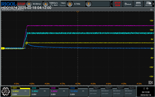
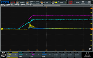
    I have observed the input, output, PG voltages, and the enable voltage. The input voltage appears to be fine, but there is no output voltage. Additionally, after powering on, the PG voltage does not go to zero. You can see the waveforms below.


    (Pink - Input, Light Blue - Enable, Yellow- PG, Dark Blue - Output)

    According to the UCC14141 datasheet, if the PG pin behaves this way, it indicates a potential fault in the FBVDD and FBVEE pins due to UVLO. I also tried reducing the R12 value and rechecked the output, but the fault persisted.

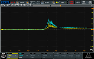
    Next, I measured the voltages at the FBVDD and FBVEE pins and observed that, during startup, these voltages rise momentarily but then suddenly drop. You can find the waveforms below.

    Based on these observations, I identified an issue with the output undervoltage protection. I measured the voltage across C283 and C284 and noticed that these capacitors suddenly discharge during the startup process. 

    To address this, I removed capacitor C283 and replaced C284 with a 0.1 µF capacitor. This resolved the issue, and I am now able to get the correct output voltages.

    However, I would like to know if removing capacitor C283 could cause any potential issues.

    Thank you again for your help!

    Best Regards,

    Sachith.

  • Hi Sachith,

    Glad you could find and resolve the issue.
    The purpose of C283 and C284 is to filter the feedback voltage. It is not needed, but recommended by the datasheet.
    See chapter 8.3.1.1 Voltage Regulation:
    "...To improve the noise immunity, a small capacitor of 330 pF should be added between FBVDD and VEE pins. Excessive capacitor slows down the hysteresis loop and can cause excessive output voltage ripple or even stability issue."

    And Chapter 8.3.1.2:

    "...TI recommends a 330-pF capacitor on FBVEE pin to filter out the switching frequency noise."

    So I think you can operate without these capacitors, but to be honest I am not sure if these capacitors are the root cause of the issue, since the same circuit works for UCC14141 on the primary side, correct?

    Also, out of curiosity, did changing C283 and C284 also resolve the issue with U39/D34? Or did you also modify  C278 and C279?

    Best regards,

    Andreas

  • Hi Andreas,

    Yes, I have changed the capacitors in U39, and it worked. The issue was with C278 and C283.

    One more thing, I'm familiar with CCS coding but not with POWER SDK. Do you know if there’s a way to access the source code for the TI DAB? I’d like to get an idea of how to develop the controller for the DAB using CCS.

    Thank you again for your support!

    Best,

    Sachith.

  • Hi Sachith,

    Okay, thanks for confirming.
    The source code is part if the DIGITAL-POWER-SDK. If you download the SDK you can import the TIDA-010054 Project to CCS and you will have all the source files. Its described in detail how to import the project and to set up the project in the design guide.

    Best regards,

    Andreas

  • Thank you very much Andreas.

    Best,

    Sachith.