This thread has been locked.

If you have a related question, please click the "Ask a related question" button in the top right corner. The newly created question will be automatically linked to this question.

UCC28950: PWM distortion

Part Number: UCC28950

Tool/software:

Hi,

Based on the schematic below, which is attached below, It is same as the EVM board.

3276.slum277a.tsc

I got some wired waveforms of PWM. Please find it attached. In the no load condition, it is in the Burst mode. But I can see the proper phase shift. However, once I add load, the PWM D(C) will be distorted. I am not sure why it is happening. 


Fig 1. PWMA(yellow) vs PWMD(green) in No load
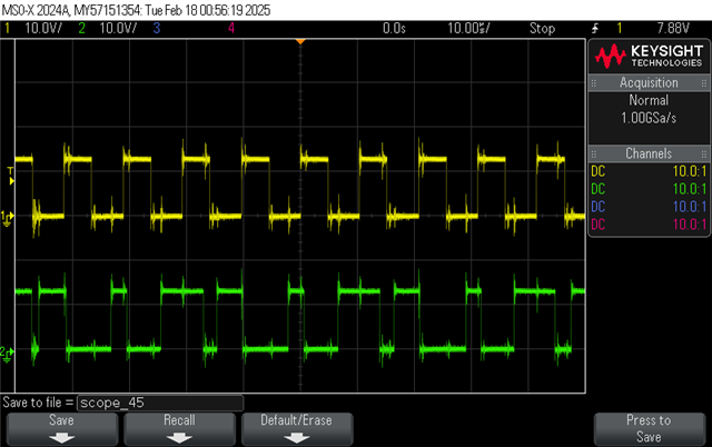
Fig 2. PWMA(yellow) vs PWMD(green) in 100mA load

Then I measured the CS pin, which gives me the waveform as below. Is it right? It is not a proper sawtooth wave, also with high frequency noise. 

Fig 3. CS pin in 100mA load

Many thanks!

Kind regards,

Zoe

  • Hello,


    Your inquiry has been received and is under review.


    Regards,

  • Hello,


    Please note that your current sense signal does not look correct.  However, this might be because your load is so low and you are just measuring noise.

    Output A and B operate at 50% duty cycle and are 50 degrees out of phase and synchronized to a master clock.  Output C and D operate at 50% duty cycle and are phase shifted to achieve duty cycle.

    When A and D are in phase the converter is at 100% duty cycle.  When B and C are in phase the converter is at 100% duty cycle.  When D is 180 degrees out of phase from A the converter is operating at 0% duty cycle.  When C is 180 degrees out of phase from B the converter is operating at 0% duty cycle.

    I looked at your waveform and it looks like out D is being phase shifting from minimum duty cycle to maximum duty cycle to a minimum duty cycle.  This will look like the on time and off time for D is 2X what it should be but it is phase shifting.

    There are few things that can cause this.

    1. Cycle by cycle peak current limit being hit (2V)
      1. Can be cause by noise on the CS pin.
      2. Can be resolved with a low pass filter. A 1 k ohm and 220 pF capacitor will generally do the trick.
    2. Voltage loop is not stability.
      1. Check loop compensation for greater than 45 deg of phase margin and greater than 3 dB of gain margin.
    3. The design does not have enough slope compensation.


    The following link will bring you to an application note that goes through the step by step design process of a PSFB using the UCC28950.  There is a section on loop compensation and slope compensation that you can use to check your designs stability.  There is also a link to the excel tool that goes along with the application note that you can use to check the design as well.

    https://www.ti.com/lit/pdf/slua560

    Thank you for interest in Texas Instruments (TI) products.  If you have a related question, please click the "Ask a related question" button in the top right corner. The newly created question will be automatically linked to this question.


    Regards,