This thread has been locked.

If you have a related question, please click the "Ask a related question" button in the top right corner. The newly created question will be automatically linked to this question.

TIDA-050026-23881: Whether or not the PSE power supply should be isolated

Part Number: TIDA-050026-23881
Other Parts Discussed in Thread: LM5165, , LM5156, TPS23861, TPS23881

Tool/software:

Hi team,

My customer is designing their PSE board and they have a general question about PSE design. Could you please answer it?

Question

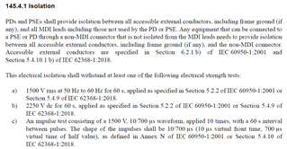
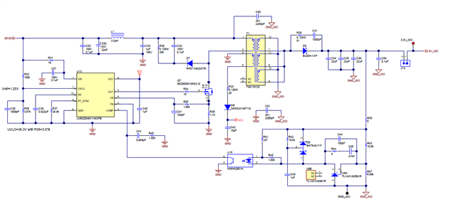
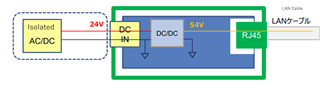
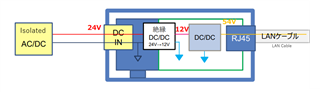
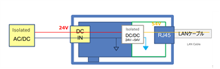
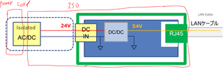
- Can Non-Isolated power IC like LM5165 be used for PSE power? Or should you use isolated power topology? When using a non-isolated power supply, it seems as if the voltages on the PSE board and the PD board will be connected as shown in the diagram below. Will this not be a problem?

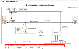
The supplementary comments for the block diagram of TIDA-050026-23881 say that "It (isolation) is not needed a real system," so I think it should be okay, but please let me know if there are any points to be careful about.

Thank you for your help.

Regards,

Taito Takemura

  • Hi Taito,

    Thanks for reaching out!

    Isolation is required for standard PSE input power. 

    Best regards,

    Diang

  • HI Diang,

    I understand the designer should think isolation of power supply of PSE and they should not use LM5165.

    By the way, what does the comments for the block diagram of TIDA-050026-23881 "It (isolation) is not needed a real system," mean? If you believe this comment, it seems like the customer can use LM5165 for the power supply, which is contradictory.

    Thank you for your help.

    Regards,

    Taito Takemura

  • Hi Taito,

    Could you let me know where you see the comments of " It (isolation) is not needed a real system,"? 

    TIDA-050026-23881 used flyback for isolation. 

    Best regards,

    Diang

  • Hi Diang,

    Could you let me know where you see the comments of " It (isolation) is not needed a real system,"? 

    The comment is below the figure 1 of Block Diagram.

    Question

    I have checked the "145.4.1 Isolation" you advised, as well as the contents of the referenced IEC 60950-1 and IEC 62368-1.
    Based on that, I think that the requirement will be met not by isolating the power supply, but by taking measures to prevent the user from touching the GND of the power supply (LM5156 GND), for example by not connecting it to the product housing or the case of the RJ45 connector. What do you think?

    Additional information about the customer's usage situation
    The PSE Controller will be TI device of TPS23861PWR. The maximum power supply will be 12W (4 x 3W devices).

    Thank you for your help.

    Regards,

    Taito Takemura

  • Hi Taito,

    PoE team is doing internal validation tests and the reply on E2E may be delayed for 3 - 5 business days. Sorry for the delay and thanks for your patience.

    Best regards,

    Diang

  • Hi Taito,

    Thanks for your patience. 

    The 3.3V VDD does not need isolation. It shares the same ground with the VPWR. In most of cases, a non-isolated LDO is used rather than an isolated DC/DC.

    From the wall power to the VPWR, normally an isolated flyback is used.  If the VPWR power is from a PD passthrough, many applications do not have isolation.

    You can use TPS23861 with class-1, which is 4W rated each port. But it must need a MCU to control TPS23861. The default autonomous mode of TPS23861 is class-4 30W.

    Best regards,

    Diang

  • Hi Diang,

    Is it correct to interpret this as meaning that if there is a place where the user can touch the power supply, such as when using wall power, isolation measures must be taken there, but if not, there is no need to worry about isolation?
    In this customer's case, wall power is not used, so regarding the power generation device for PoE power supply, is it correct to understand that it is not necessary to isolate the primary input side and secondary output side, and that the LM5156DSSR can be used in a non-isolated state for a power generation device for PoE power supply?

    Thank you for your help.

    Regards,

    Taito Takemura

  • Hi Taito,

    PoE team is doing internal tests and the reply on E2E may be delayed for 3 - 5 business days. Sorry for the delay and thanks for your patience.

    Best regards,

    Diang

  • Hi Taito,

    Your description may be correct but standard will always require isolation as its description.

    Is it correct to interpret this as meaning that if there is a place where the user can touch the power supply, such as when using wall power, isolation measures must be taken there, but if not, there is no need to worry about isolation?

    Is LM5156DSSR a flyback to generate 3.3V (TPS23881's VDD) or 54V (TPS23881's VPWR) ? The 3.3V generation does not need isolation. The 54V generation from grid normally need an isolation.

    Best regards,

    Diang 

  • Hi Diang,

    Option 1: The LAN connector and the metal case are at the same potential. The LAN connector is isolated inside the board.

    [Question 1] Since the GND of the PoE power supply goes out of the product from the power connector, is it correct to understand that it is necessary to take measures to prevent users from touching it even within the blue dotted line?

    [Question 2] Would the configurations of options 2 and 3 be possible? Also, I would like to know the recommended configurations for options 1-3.

    Option 2: Insulate the power supply of the input part of the board.
    The GND of the input part, the case, and the LAN connector are at the same potential.

    Option 3: Insulate the power supply of the POE.
    The GND of the input part, the case, and the LAN connector are at the same potential.

    Thank you for your help.

    Regards,

    Taito Takemura

  • Hi Taito 

    Thanks for your reply. We will take a look on your question and get back to you in 3-7 business days. Thanks for your patience.

    Best regards,

    Diang

  • Hi Taito,

    Thanks for your patience. 

    If I understand correctly your 24V output AC/DC already has an isolation as 145.4.1. If so, you do not need additional isolation, may need a boost the 24V to 54V using non-isolated converter, and an regulator to transfer either 54V or 24V to 3.3V. In this case, 3.3V, 24V, 54V shares the same ground that is isolated with the AC side ground.

    Best regards,

    Diang  

  • HI Diang,

    [Question 1] Since the GND of the PoE power supply goes out of the product from the power connector, is it correct to understand that it is necessary to take measures to prevent users from touching it even within the blue dotted line?
    Regarding Question 1 above, I understand that the answer is yes and that it is necessary to take measures to prevent users from touching the blue dotted line areas, but please let me know if I have misinterpreted the above.

    Thank you for your help.

    Regards,

    Taito Takemura

  • Hi Taito,

    Thanks for your reply!

    We will look into your questions and get back to you in 3-7 business days.

    Best regards,

    Diang

  • Hi Taito,

    Thanks for your patience. 

    My understanding is AC is with the power cord that need human touch to connect, then after the AC/DC it is isolated.

    Best regards,

    Diang