This thread has been locked.

If you have a related question, please click the "Ask a related question" button in the top right corner. The newly created question will be automatically linked to this question.

PMP23200: PMP23200

Part Number: PMP23200
Other Parts Discussed in Thread: TPS7H5001-SP

Tool/software:

Hi!
1) for T101 how was it sized with R102=0.3 ohm
R102 = V43*Nsec(50)/I21
how was R102 sized ?
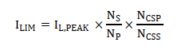
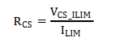
R101 = VCS_ILIM(1.05)/I21
how was R101 sized ?


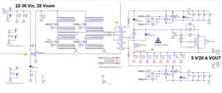
2)  why SW is not connected to GND ?
when D102 unpopulated, how would the diode be connected to LC filter ?
Vout=2*Vin*Nsec/Npri*d
is this rule valid ?

  • Hello,

    1) R102 was selected to reset the core during the primary FET dead-time. The value was derived empirically. R101 was selected to be roughly half of the OCP level at max load.

    2) The secondary switch node is not connected to ground, that nodes is the waveform that goes into the LC filter to make the output voltage. Note that the secondary rectifiers are synchronous, driven w.r.t. GND. D102 was meant for a voltage clamping circuit to reduce ringing on the secondary. In practice we found that diode ORing via D301 and D302 was a better approach.

  • hi,
    1) I thought this transformer should sense the current and give it to PWM controller for feedback or OCP,  I thought R102 is based on the equation in the data sheet of this transformer, please see below. 
    the thing is this equation wont give the R102 we have in the SCHEMTIC; can you clarify that please ?

    for R101, I thought it should be sized based on this equation


    ILpeak should be 35A, Ns=2,Np=6, NCSP=1,NCSS=50 this will result in 0.23A.
    Rcs = 1.05/0.23=4.5 ohm not 0.3.
    did I miss something ?

    2) in the application note it was mentioned that A resistor-capacitor-diode clamp circuit can be used to limit the voltage at the switch node, does this RCD correspond to D103 and the R & C to the right ? 
    the same applies to D105.
    what is the difference between this RCD and the OR-ing of D301 & D302 ?

    BR,
    Mohamed

  • Hi Mohamed,

    1) The information on the datasheet was more for a sample test they use to verify functionality as a current sense transformer. The equations found in the datasheet were used to determine the R101 value. R102 is used to demagnetize the core during the dead-time. This is needed since the current sense transformer only sees positive current on the primary side and thus needs do demagnetize to prevent saturation.

    2) The applications section of the TPS7H5001-SP datasheet is considering a push-pull topology with a RCD clamp on the primary side. This is typically needed for that topology, but a full-bridge will not need a clamp on the primary side. Both typologies will need some clamp or snubber on the secondary side. There are many circuits that can be used, the D301 and D302 ORing to a RC is one option to reduce ringing.

  • Hi John,
    1) How to choose the value of R102 ?
    if the equation in the datasheet is for R101, why the value I got from my calculations is different than the Schematic ?
    2) agree but why then is the Cap before the Resistors ? should the position be changed to have RC network ?

    BR,
    Mohamed

  • Hi Mohamed,

    1) R102 is chosen empirically, it is tougher to calculate because that resistor is used to dampen energy caused by parasitics in the transformer and PCB. For R101 I added margin to the ILIM to allow for a higher output current before the OCP is tripped.

    2) You could have the cap and resistors in parallel with each other, the other side can be a DC node, so either the VOUT or SGND nodes would work.

    Thanks,

    John