This thread has been locked.

If you have a related question, please click the "Ask a related question" button in the top right corner. The newly created question will be automatically linked to this question.

PMP23069: runCurrentLoop() function

Part Number: PMP23069


Tool/software:

Hi Team,

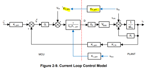
For the “runCurrentLoop()” function, after the PI the gi_out term is added to the instantaneous AC voltage divided by the bus voltage. Is there a reason why this was chosen as opposed to a more traditional average current mode control loop? Just trying to understand the pros and cons

  • Hi Team,

    Any update?

  • Alex,

    I will recommend you to go though the Ti traning series of high density PFC especially part 2 for the detailed explanation of the reason behind gi_out term is added to the instantaneous AC voltage divided by the bus voltage:

    https://www.ti.com/video/series/digitally-controlled-high-efficiency-and-high-power-density-pfc-.html

    In short, the reason behind adding AC voltage term is to provide feedforward to compensate any changes in AC input voltage. Sum of these two is then divided by DC bus feedforward term to accommodate any sudden changes in VBUS due to load change. This simplifies inner current loop which can be compensated by simple PI controller. In other words, rather than relying on just traditional inductor current change (effect) due to change in either VAC or VBUS side (cause), we are including these "cause" terms itself in feedback loop for faster response towards the error correction. 

    You can refer to User guide, Page 9 for the explanation/diagram of the current loop as well: https://www.ti.com/lit/ug/tidud61e/tidud61e.pdf

    Let me know if this clarifies your query.

    Regards,

    Sumit

  • Two emails on this that Id appreciate your reply on.

    1) That explanation is why we asked. The block diagram in the User Guide does not match what is going on in code, and has a few other issues.

    In traditional ACMC, the Vbus and VAC terms in the feed forward are averaged. The issue that we see with the instantaneous approach is when line oscillations occur on the line or when line quality is not perfect coming into the unit.

    Is the PI controller the reason for going with this method instead of traditional ACMC? My colleagues all come from analog backgrounds so the increased complexity of tuning a 2P2Z controller is fine. Just wondering if this a path TI had gone down and found didn’t work for one reason or another.

    2) Is this a typo? Should it be “Kvac_gain”?  I believe the Gi term is added to Vin(t)/Vout(t).

    I understand that this approach improves transient response, but it also creates a duty cycle that can be “instantly” changed by disturbances on the AC line. Traditional average current mode control is terrific in this regard because it integrates the inductor current making it extremely robust and noise immune.

    We’re noticing that if the AC sense has any sort of oscillation or disturbance that is beyond the bandwidth of the Gi PI filter, it directly manipulates the duty cycle. These abrupt changes in the duty cycle result in a discontinuous change in inductor current which in turn causes AC sense disturbances, and the cycle repeats, this is a form of positive feedback.

  • Alex,

    1. This code utilize Software Phase Locked Loop getting extracting sinusoidal term from AC line voltage. Instantaneous current reference value (TTPLPFC_ac_cur_ref_inst_pu) for inner current loop is obtained by multiplying current reference (TTPLPFC_ac_cur_ref_pu) value with that sine term obtained from SPLL. The current reference term is obtained by multiplying output of voltage loop pi compensator (TTPLPFC_gv_out) multiplied by average bus voltage (TTPLPFC_vBusAvg_pu obtained by exponential moving average and notch filter) and divided by rms ac voltage (TTPLPFC_vRmsAvg_pu using power measurement library). This way of implementation avoids the oscillations that you have mentioned and PI controller is fine for that. This instantaneous current reference is fed to PI controller with sensed current which will will provide TTPLPFC_gi_out term which is used to calculate duty as follows

    TTPLPFC_dutyPU = (TTPLPFC_gi_out + (TTPLPFC_ac_vol_sensed_pu * TTPLPFC_VAC_MAX_SENSE / TTPLPFC_VDCBUS_MAX_SENSE)) / (TTPLPFC_vBus_sensed_pu);

    2. Yes that should be "Kvac_gain" as shown in "where" section just above the diagram in the user guide. 

    Regards,

    Sumit