This thread has been locked.

If you have a related question, please click the "Ask a related question" button in the top right corner. The newly created question will be automatically linked to this question.

UCC28950: Regarding the isolation transformer for the current sense line of the UCC28950

Part Number: UCC28950
Other Parts Discussed in Thread: UCC27714EVM-551

Tool/software:

Hi team,

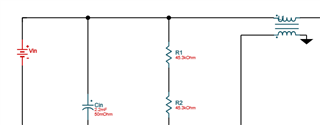
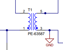
I have a question regarding the isolation transformer for the current sense line of the UCC28950.

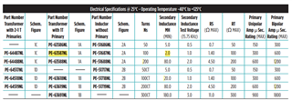
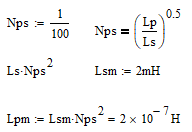
Since the purpose of this isolation transformer is to provide isolation between the primary and secondary sides, is it acceptable for both the primary and secondary inductance values to be 20mH?

In WEBENCH, Lp is specified as 20mH.

Best regards,

Kyohei

  • Hello,


    I think this question is related to the UCC28950.  Can you clarify?


    Also, can you provide the Webench file?


    Regards,

  • Hi Mike,

    Thank you for your reply.

    I'm sorry, I would like to discuss the UCC28950.

    The WEBENCH file can be found at the following URL.

    https://webench.ti.com/appinfo/webench/scripts/SDP.cgi?ID=F48C0D08BA56D466

    Best regards,

    Kyohei

  • Kyoshi,

    L1 in your design is to sense the input current. I am not sure what you are asking.

  • Hi Ning,

    I understand that L1 is for sensing the input current.

    My customer asked about the constant of the current sense L1.

    In WEBENCH, the Lp of L1 is 20mH, and in the EVM component, the Ls is 20mH. How should the constant be designed?

    Is it okay for both Lp and Ls to be 20mH?

    Best regards,

    Kyohei

  • Can you share which EVM has a 20mH Ls?

    Do you mean this one in https://www.ti.com/tool/UCC27714EVM-551?

  • Hi Ning,

    Thank you for your reply.

    The PE-63587 on the UCC27714EVM-551 has an Ls of 20mH. Is it okay for both Lp and Ls to be 20mH?

    Best regards,

    Kyohei

  • PE-63587 Ls is 2mH, not 20mH

  • Hi Ning,

    Thank you for your reply.

    As shown in the attached diagram, Ls is 2.0mH. Is it correct to understand that the basic design with Lp:Ls = 20:2 is acceptable?

    Best regards,

    Kyohei

  • Hello,

    If the turns ratio is Nps = 1/100 the primary magnatizing inductance should be 200 nH.  Please see the math below.

    When it comes to current sense transformers the primary will always have less turns than the secondary.  You are trying to produce as little voltage drop as possible on the high current side.  So Lp and Ls should not be the same.  That would give a turns ratio of 1.

    Regards,

    Mike

  • Hi Mike,

    Thank you for your response.

    I have obtained the customer's WEBENCH design data and would like advice on selecting a current transformer.

    I will send the data via private message, so please approve the friend request.

    Best regards,

    Kyohei

  • Hello,

    Your inquiry will be reviewed and answered in the order it was received.

    Regards,

  • Hello,

    Thanks for letting me know.  

    Regards,

  • Hi Mike,

    I would like you to review my customer's WEBENCH design data and provide advice on the constant design of the current transformer.

    I will share the design data via private message, so could you please accept my friend request?

    Best regards,

    Kyohei

  • Hello,


    I can see from your profile that you are distribution applications engineer.  This is a public forum and all reviews will be handled on the e2e.  If you need private support please contact your local field office and get in touch with a field application engineer for direct support.


    In regards to the Webench design.  You and the engineer that you are supporting can review and check the design with application note that can be found at the following link.  It goes through the step by step design process of a PSFB using the UCC28950.  There is also a link in the excel design tool inside the application note that uses the same equations.  There is also information in the application note on to selected transformer turns ratios and calculate RMS and peak currents.  We generally give this information to magnetic design houses like Wurth and Renco to design the transformers for are reference designs.

    https://www.ti.com/lit/pdf/slua560


    There is guidance in the data sheet regards to doing the layout.  However, you might want to take a look at the 600 W reference design that you can find at the following link.  You can use as a reference while doing your design.

    https://www.ti.com/lit/pdf/sluub02


    Regards,

  • Hi Mike,

    Thank you for your support.

    Based on the information provided, it seems that an appropriate winding ratio for the current transformer can be derived.

    Since it is a current conversion, if the winding ratio is correct, can the inductance values for both the primary and secondary sides be selected with reference to tools like WEBENCH without any particular issues?

    Best regards,

    Kyohei

  • Hello,


    Your inquiry will be reviewed and answered in the order it was received.


    Regards,

  • Hello,

    Not that I know of.

    Regards,