This thread has been locked.

If you have a related question, please click the "Ask a related question" button in the top right corner. The newly created question will be automatically linked to this question.

TIDA-010054: Access to Additional Files

Part Number: TIDA-010054

Tool/software:

Hi!


Thank you in advance for your help. I would like to make some slight modifications to the reference design and I wanted to know if it was possible to get access to a few more files for a quick turn around? Could you please provide the following files
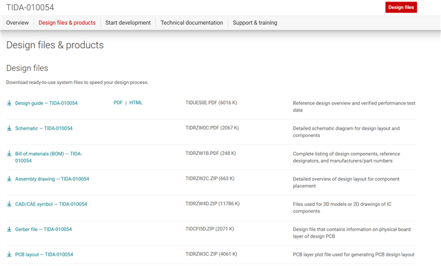

- BoM in Excel format
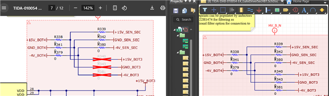
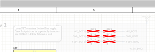
- Altium Schematic Docs (or other schematic file that is not a pdf)
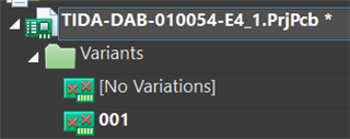
- Altium PCB Docs (I only see a pdf under PCB layout)
- Any other Project Docs (I see a mention to Altium data base in another questions but I do not see where we can access it)


Thank you,

  • Hi,

    Thanks for reaching out.
    All the requested files are available  on the reference design page: https://www.ti.com/tool/TIDA-010054#design-products


    Altium files are under CAD/CAE symbol.

    Best regards,
    Andreas

  • Thank you .

    I don't believe the excel BOM is on there.  I would appreciate it if you have an excel version of it. 

    Would you be able to share the MATLAB Script file which was mentioned in the Design Resource under 2.3.4.5 Capacitor Selection ?

    Also is there any microcontroller code you can share? 

    Thank you!

  • TIDA-DAB-010054E4(001)_BOM.xlsx

    Hi,

    Please find the excel version attached.
    The MATLAB script is no longer available. I recommend using the PLECS simulation deck which is available on ti.com as well to simulate critical operating points. This will lead to much better results since parasitics can be included as well.

    Best regard,

    Andreas

  • Thanks!

    Can you please also send a CPL file (aka Pick-and-Place file)? 

  • Hello,

    Sure, find the pick and place file attached.

    Best regards,

    Andreas
    Pick and Place File.zip

  • Thanks! A few more questions, . I really appreciate your help.

    1. Are D24, D28, D29, D30 populated or DNP? I see them populated on the PCB and on the schematic doc within the Altium project, but I see them DNP on the Schematic PDF provided by TI: https://www.ti.com/lit/df/tidrzw0c/tidrzw0c.pdf?ts=1744531146871 

    Pic of D24 populated on Sch Doc

    Pic of D24 NOT populated on TI Schematic PDF

    Could you please tell me which one it is?

    2. There is also a difference for R219,R221,R224-R225,R227,R229. The Schdoc within the Altium Project on the right shows zero ohm resistors but the schematic pdf shows DNP.

    3. And for R340,R343,R381 as well. The Schdoc within the Altium Project on the right shows zero ohm resistors but the schematic pdf shows DNP.

    4. Which is more up to date, the schematic provided by TI or the schematic doc within the Altium project? I noticed discrepancies between the two. 

    Thanks!

    Carla 

  • Hello,

    1. D24, D28, D29, D30 can be DNP. This is a optional bootstrap, but we did not use it so far. 
    2. In Altium you need to switch to variant 001 and from editor view to the schematic view as shown below, then the DNP parts will be shown as DNP
           a. Select variant:

           b: Switch to schematic view:

           c: See DNP Parts:


    3.Same as 2
    4. The schematic PDF is create from this exact Altium file using variant 001. 

    Best regards,
    Andreas

  • Thanks for all your help! Could you please tell me what the part numbers are for the following parts? I don't believe they were on the BOM but I see them on the picture

    • The heat sink on the transformer
    • Screws on the heat sink
    • Connectors on the heat sink
    • Plastic black tubing
    • Fiberglass

  • Hi,


    Your welcome. Find my answers below:

    • There is no heatsink on the transformer. The aluminum casing provides enough cooling. 
    • The heat sinks are  CR201-50VE from Ohmite. They can be found on the BOM under MP3, MP6, MP7 and MP10
    • We did not use any screws on the heatsink, we use CLA-T247-21E clamps to fix the FETs on the heatsink.
    • Between the MOSFETs and the Heatsinks we use isolated thermal pads CD-02-05-247 which can be found on the BOM under MP1, MP2, MP4, MP5, MP8, MP9, MP11, MP12.
    • Please clarify to which black tubing and which fiberglass you are refereeing.