This thread has been locked.

If you have a related question, please click the "Ask a related question" button in the top right corner. The newly created question will be automatically linked to this question.

PMP23454: Clarification on 0V Output Control in Trickle-Charge Mode Using UCC256604 in PMP23454

Guru 12020 points
Part Number: PMP23454
Other Parts Discussed in Thread: LM317

Tool/software:

Hi,

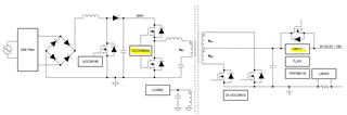
I am currently evaluating the feasibility of implementing low-voltage (near 0V) output control using UCC256604 in an LLC topology.

In the PMP23454 reference design, it is documented that the output range of 0V to 12.5V is supported in trickle-charge mode. The design report also shows waveforms at 0V output with a 165mA load.
However, since an LM317 is placed downstream in the output stage, I would like to clarify the following technical points:

Questions:

An LM317 is connected after the LLC converter. Is the "0V output" achieved by adjusting the LM317, or is it possible to adjust the UCC256604 itself to around 0V? If it is achieved by adjusting the LM317, is the lower limit of the LLC converter's adjustment down to 7.5V, as indicated for normal charging?

Thanks,

Conor

  • Hi Conor,

    The LM317 is configured as a current source that regulates its current to 165mA. In trickle charge mode, if the load pulls less than 165mA the output voltage will equal the output voltage of the LLC minus the headroom of the LM317. The use case for this design is a deeply discharged battery that has not been charged in a very long time. The battery will look like a constant voltage load and the LM317 charges the battery with this small current until the pack voltage is high enough to safely take the full charging current. For your use case, it may make sense to configure the LM317 as an LDO instead and then you can adjust the FB divider going to LM317 to adjust the output voltage. 

    Yes, in PMP23454 the lower limit of the LLC output voltage is 7.5V. The reason for this is because this design does not have an auxiliary supply. In order to keep the LLC alive when the output is near 0V, the primary and secondary side circuitry would need to derive its bias from some other voltage in order to properly regulate the output. 

    Best Regards,

    Ben Lough