Part Number: TIDA-050023
Tool/software:
Hello,
We created a PoE++ prototype which should handle an output of round about 12V @ 4A similar to TIDA-050023 reference design.
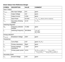
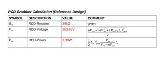
For the primary RCD-Snubber we used values provided from TIDA-050023 but we wonder about the 39kΩ used for the RCD-Resistor. When we calculate the power losses of the RCD-Snubber using the values given by TIDA-050023 and formulas given by application note AN4147 we get:
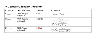
- RCD-Voltage: ~360V
- RCD-Losses: ~3.4W.
These values seem to be much to high because the primary MOSFET and the RCD-resitor given in the reference design can only handle 150V and 0.25W (neglected that 3.4W losses seems to be much to high from the efficiency-view)
We tried to calculate the RCD-Resistor more properly to get a RCD-voltage fitting for the MOSFET but then the calculated RCD-losses increases to round about 4.8W.
It seems that the RCD-circuit is theoretically not realizable using the given parameters of TIDA-050023.
How could the RCD-circuit of TIDA-050023 work without affecting the MOSFET and the RCD-resistor?
Are we missing something when we using the formulas given by AN4147?
Bellow you can find our calculations to make it more clearer.
FYI: Our design use the following main parts:
-
primary MOSFET: BSC093N15NS5ATMA1
-
transformer: PA1736NL
-
secondary MOSFET: BSC027N04LSGATMA1
-
synchronous rectifier: UCC24610
Best regards
Janis