This thread has been locked.

If you have a related question, please click the "Ask a related question" button in the top right corner. The newly created question will be automatically linked to this question.

PMP22951:Questions about Interconnect PCB and Firmware Availability

Other Parts Discussed in Thread: PMP22951, PMP23126

Číslo dílu: PMP22951

Hi TI team,

First of all, I would like to thank you for the excellent work on the PMP22951 reference design. It looks very well thought out and extremely useful for high-efficiency power supply applications.

I have a few questions regarding this design:

In the PMP22951 documentation, it seems there is a small break-off PCB in the top right corner that is intended to connect the transformer (PAT6289NL) to the SR card. However, in the photographs of the assembled board, this interconnect PCB looks different — it has rectangular holes for the SR card connections instead of the round ones shown in the PCB design files. Could you clarify which version is correct and if there is an updated design for this interconnect? 

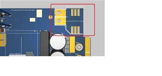
Will the firmware for PMP22951 be made available, similar to the way it is provided for the very similar PMP23126 design? If so, could you please share an expected timeframe?

Additionally, could you please specify the heatsink models or part numbers used for the SR card and the primary GaN card in the assembled PMP22951 unit?

Also, on the assembled PMP22951 board, there is a yellow wire passing through CT100 and connected in place of CT101. Could you please explain what this modification is for? 

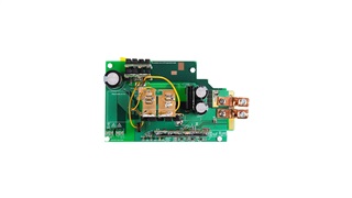
In the Altium Files rev.E - Project Outputs, there is a schematic file named PMP22951E(001)-Sch where components like T100, L100, L102, and others are not populated. Is this the final version of the design, or some kind of modification?

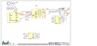
Thank you very much for your support and for providing such great resources!

Best regards,
Jaroslav D

  • Hi Jaroslav,

    1. The square PCB is what was used in the design. The small breakout board was for a different SR card that was using silicon SR FETs. 

    2. I believe the FW is not planned to be added to the digital power SDK but it can be shared via MySecureSoftware.

    3. The primary side GaN daughter card is the same daughter used in PMP23126. The heatsink part number is S05MZZ2F from Alpha Novatech. Let me find the SR GaN heatsink part number and get back to you.

    4. This was to allow for the option to test with the current sense transformer either on the primary winding or in between the input caps and the primary side full bridge.

    5. T100 and L100 are both populated on the board. L102 was an option to place the current sense transformer on the secondary winding but this was ultimately not used in the final design.

    Best Regards,

    Ben Lough

  • Hello Ben,

    thank you very much for your detailed answers.
    I would like to kindly follow up with a few points:

    1. Would it be possible for you to provide the Gerber files specifically for the square PCB used in the final hardware (for the interconnect board)?

    2. I have already submitted a request for access to MySecureSoftware via the online form.

    3. Regarding the heatsinks — I would really appreciate it if you could provide the part numbers. I was not able to find the S05MZZ2F from Alpha Novatech in their catalogs or online distributors.

    Thank you again for your support and for sharing your excellent designs!

    Best regards,
    Jaroslav Dospisil

  • Hi Jaroslav,

    1. Below is the interconnect board for connecting the transformer to the EPC SR card:

    /cfs-file/__key/communityserver-discussions-components-files/234/PMP22951-MX7-DC.zip

    There is an interposer card in between the SR card and main board to make it easy to plug into J102. Just in case it wasn't in the online files, Below is a zip containing the interposer: 

    /cfs-file/__key/communityserver-discussions-components-files/234/EPC-SR-Interposer.zip

    3. Below is the datasheet for S05MZZ2F. Let me find the material for the SR heatsink and get back to you.

    /cfs-file/__key/communityserver-discussions-components-files/234/S05MZZ2F.PDF

    Best Regards,

    Ben Lough

  • Thank you again, Ben, for providing the Gerber files, interposer files, and the heatsink datasheet — I really appreciate your quick support.

    I would like to kindly ask one more detail regarding the SR card connection:
    Are the SR card and the SR interposer simply soldered together via the pins, or is there a connector used between them?

    Additionally, if you happen to have any high-resolution photos of the fully assembled design showing the connections between all the boards, I would love to take a look at them.

    Thank you once more for your assistance and for sharing these excellent resources!

    Best regards,
    Jaroslav 

  • Hi Jaroslav,

    Below is the datasheet for the SR heatsink.

    /cfs-file/__key/communityserver-discussions-components-files/234/S08EHS0B.pdf

    The SR card and SR interposer are soldered together. There wasn't a convenient connector between these two unfortunately.

    I don't think I have any better resolution photos of the board unfortunately.

    Best Regards,

    Ben Lough