Tool/software:
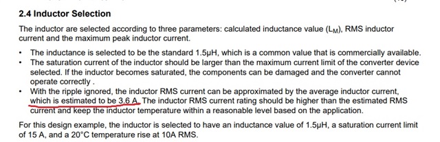
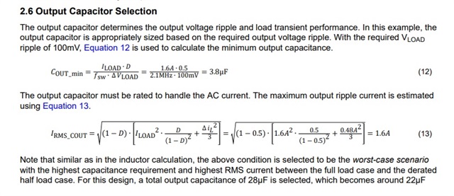
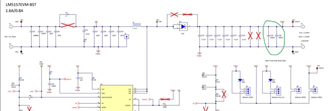
In the LM51581-Q1 boost converter design application note, how was the inductor RMS current calculated as 3.6 A? Also, the minimum output capacitance Cout_minC_{\text{out\_min}}Cout_min was calculated to be 3.8 µF, but 28 µF was selected—why was such a large value chosen? Additionally, the schematic includes two 100 µF capacitors at the output. Why were they added, and how was their value determined?can you please clarify this?