


Tool/software:
Hello,
In Lab 5, it is stated that when starting in PFC mode under 30 Vrms/60Hz input, setting clearPWMTrip = 1 should cause the DC bus voltage to increase slightly. However, during my test, I only observed a voltage increase from 70 V to 82 V when AllRelaySet = 1 (i.e., when the relay was closed). After setting clearPWMTrip = 1 and enabling PWM outputs, I did not observe the expected slight voltage boost.
Additionally, when monitoring the angle lock using CCS graph, I noticed that the SPLL angle appeared to be approximately 120° off from what is described in Lab 5.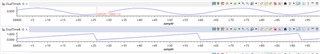 Vgrid A & PLL Angle
Later, I tried using the following:
TINV_dVal1 = TINV_vInv_dq0.a;
TINV_dVal2 = TINV_angleSPLL_radians / (float32_t)(2.0f * TINV_PI);
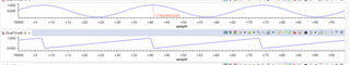 vInv_dq0.a & PLL Angle
With this, the graph matched what is shown in Lab 5 — specifically, where the PLL angle equals 0 when Vgrid is at its peak.
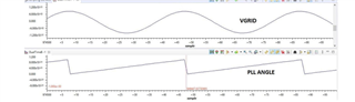 Lab 5 example
I would like to confirm:
In Lab 5, is the SPLL angle expected to be aligned with the Vgrid voltage peak, or with
TINV_vInv_dq0.a?
Could you please clarify which waveform the SPLL angle is locked to in the reference code? Thank you very much!
