Other Parts Discussed in Thread: TMS320F28379D
Tool/software:
Hello,
I'm testing with a previous version of the board..
I have some questions about Lab 4.
First,
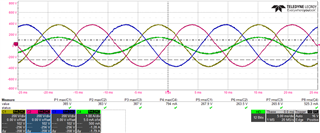
Fig 1. Lab 3(Current control) Voltage and current waveform with 500 ohm resistor(Y-connected)
The switching frequency is 100 kHz, Vdc = 750 V and idref_pu = 0.02(current loop ISR runs at fsw)
Each gain of the PI controller is set to Kp = 6, Ki = 0.006 (because I can get best waveform under this condition shown as Fig 1)
So, I moved on to Lab 4
As shown in the design guide, Slowly ramp thd DC bus voltage to 750 V, Enter "1" on TINV_startPowerStage variable. As soon as ramp the AC voltage of the grid to 220 Vrms, I also turn on the relay.
After the relay was connected, the gate driver's dsat LED was turned on, I can observe the grid over current flag is set to "1".
I guess this situation happened because the response to the current controller in the AC power supply was different from resistance load, and I used the PI controller gain provided by design guide. Under this condition, the result is same as previous test..(so sad)
I changed Vdc 100 V and Vrms 30 V and start Lab 4. (same results.. dsat LED was turned on and iGrid over current flag..)
From what I understand, when the TINV_startPowerStage variable is set to "1", measure the grid voltage and start current control loop and PWM operation if the previous vGrid value is negative and the present value is positive(zero crossing??).
I think the current control loop and PWM operation is started in spite of the PLL is not locked. So, I changed the sequence.
1. Slowly ramp the Vdc to 100 V
2. Ramp the Vac to 30 Vrms(when the d-axis of grid voltage is bigger than the value that I set, the relay is on automatically)
3. Observe the graph in CCS debug window to confirm the PLL is locking
4. When the PLL is locking on the Grid voltage, set TINV_clearPWMTrip to "1"(also current loop is started)
In this sequence there is no dsat LED turn on, no grid over current flag.. but the current waveform is not normal shown as Fig 2, Fig 3.
Idref_pu is set 0.0023(0.0023*32 = 0.0736 A).

Fig 2. Grid current waveform as soon as current loop and PWM operation starts(trigged)

Fig 3. Same as Fig 2(trigged)
When I change the Kp and Ki, the current waveform is changed.
With Vdc 750 V, Vac 220 Vrms was no dsat LED turn on but, iGrid over current flag is turned "1".
(I read the datasheet of UCC21710QDWQ1 and it said high di/dt of drain to source can cause voltage bounce because of parasitic inductance of shunt resistor(I think this works the same way when detecting OC with resistance divider of TIDA-01606's gate driver) and board layout parasitic which results in false trigger of OC pin. Is there a possibility that the current control and PWM operation will start with the PLL is not locked normally, resulting in high di/dt?)
Is the sequence that I changed correct?
If the sequence I changed is right and the only problem is gain.. I can tune the gain of the PI controller to get the clear sine waveform and I'll going to increase the Vdc to 750 V, Vac to 220 Vrms and tune the PI controller again.
Thankyou and Have a good day!
-Chaehyun