This thread has been locked.

If you have a related question, please click the "Ask a related question" button in the top right corner. The newly created question will be automatically linked to this question.

TIDA-010016: The function of current sink

Part Number: TIDA-010016
Other Parts Discussed in Thread: TIOL111, TIOL112

Tool/software:

Hi team,

My customer is looking into the reference design TIDA-010016.

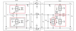
They have one support need from your team, pls see below picture:

  1. What's the function of the red blocks in below picture?
  2. How to turn the status from on and off?
  3. When turn on, how could device work to have the signal (VRQLM, IQLM, IQPKLM) and how could it work?
  4. Could you give the detailed explanation on this?

If it is related to IO-Link device, you can loop IO-Link AE into this case. Thanks.

Joyce

  • Hi Joyce,

    happy to support you!

    First, I would recommend to look at https://www.ti.com/tool/TIDA-010234, this has the same function but newer devices and better support.

    Your questions are related to the IO-Link standard, so I would also check the specification for details: https://io-link.com/share/Downloads/Package-2020/IOL-Interface-Spec_10002_V113_Jun19.pdf

    The blocks on the very right and left are the actual transceiver transistors, pulling the line high or low. You turn on only one of them at any time. These are integrated in TIOL111 or TIOL112 and the logic there takes care that you do not short the lines together.

    The other block in the red circle is a current sink, that is part of the master transceiver. This helps communicate with very simple devices that can only drive the line high, but not low. This current sink is integrated in TIOL112 and activated automatically if the master mode is selected.

    I hope this helps you!

    Best regards,

    Steffen