This thread has been locked.

If you have a related question, please click the "Ask a related question" button in the top right corner. The newly created question will be automatically linked to this question.

ADS1235EVM: Unable to read strain gauge values from the ADC pins

Part Number: ADS1235EVM
Other Parts Discussed in Thread: ADS1235

Tool/software:

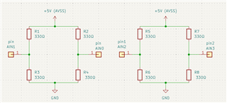
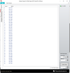
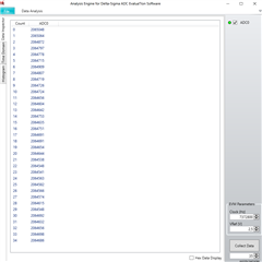
Hi there , i have recently acquired an ADS1235EVM board and am trying to use it to monitor variation from my strain gauge set up. The strain gauges work perfectly. Each strain gauge in my Wheatstone bridge (4 strain gauges) have been correctly connected to pins AIN0-AIN3. I've then set these pins to GPIO output in the register map. However , i am struggling to figure out how exactly to monitor these ADC pins live or how to get them to show up in the data analysis tool. Please assist with how to properly configure these pins and read live values. 

Thank you

  • Hi Luke Oberholster,

    Why are you setting the AINx pins to GPIO and setting them to outputs? The ADC measures the differential voltage between the channels you select in the INPMUX register

    Can you provide a connection diagram of your system? It could also be useful if you can send a picture of how you have connected the strain gauges to the EVM

    Also, note that the EVM can only view the data for one channel at a time. So you will have to measure one channel, view the data, then go back to the main page of the GUI to select the next channel, the measure that channel, and so on

    -Bryan

  • Hi there Bryan

    Thank you so much for the response !

    I have uploaded an image of how I've connected my Wheatstone bridges to the board. What you will see is that i wired the AVSS and GND to provide power and then connected the sensing pins to pins AIN0-AIN4. In the additional image provided i have set my "points/samples" to 35 as a test as well as set the INPMUX --> MUXP (AIN0) & MUXN (No connection) . Additionally i set MODE2 --> GPIO_CON[0] to AIN0 and then set GPIO_DIR[0] as an input (I'm unsure if this is necessary). No MODE3 changes have been made. Currently in the photo of the data analysis tool ,  I'm measuring values which I'm assuming to be for my connection at AIN0 , is this assumption correct ? 

    Also , based on my connection diagram , am i only able to read the values of one Wheatstone bridge at a time by measuring AIN0 at MUXP and AIN1 at MUXN , would tis be correct usage of the pins ?. 

    Additionally , am i correct in assuming that i should be measuring MUXP of AIN0 and MAXN of AIN2 to obtain the combined strain reading of both bridges , or is this incorrect.

    Apologies for all the question and once again i am very grateful for the assistance.

    Thanks ,
    Luke


    Connection diagram


    Samples when no load is applied MUXP --> AIN0


    Samples with load applied (MUXP --> AIN0)


    Samples with MUXP --> AIN1 and MUXN --> AIN0 (with load applied) . At no load the values were around 200.


  • Hi Luke Oberholster,

    Can you provide your complete schematic? I am concerned that you have +5V as your AVSS net, whereas AVSS on the ADS1235 should be the lowest voltage (ground if using a unipolar supply, down to -2.5V relative to ground if using a bipolar supply)

    Can you send a screenshot of the register settings from the GUI so we can review?

    In the INPMUX register you can select a single channel pair e.g. AINP = AIN0 and AINN = AIN1. So you can measure 1x load cell at a time, then you would need to change the selections in the INPMUX register with a WREG to be able to measure the second load cell.

    In a real system you can execute this programmatically in your code e.g. change INPMUX, start conversions, read data, change INPMUX again, start conversion, read data, etc. The GUI only allows you to read one channel pair at a time, so you need to perform the aforementioned actions manually

    -Bryan