Tool/software:
Hi,
I purchased the TIDA-010042 MPPT PCB and used the design files from the official reference design on TI.com. I received the board and verified that the converter works by manually coding specific PWM values — everything functioned as expected. I then flashed the available firmware version V2.0, which appears to be the only and latest version.
I tested the board in two different setups:
-
Using a homemade PV emulator – a programmable DC power supply running an algorithm to emulate a PV panel with an open-circuit voltage of 35V and short-circuit current of 3.5A. I used an electronic load (E-load) in constant voltage (CV) mode at 22V to simulate the battery. The board was connected to my computer via LaunchPad for debugging.
-
Before starting, the firmware showed the system was in
Wait_state, as expected (attempting MPPT every 4 seconds, but remaining in wait state due to no current flow). -
I powered the E-load first, then the PV emulator. However, no current flowed. There is two "mode that take place every 5s, the first one in which the Output current is equal to 0A and voltage is around 20V (!=the CV voltage). And the other one during which hear a buzzing sound around 30 Hz (maybe the vibration of a component), the outpout voltage drops to 0V and a very small current is drawn (0.1A).
-
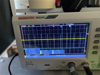
Using an oscilloscope, I observed the second state : output voltage is 0V most of the time, but at a frequency of 30 Hz, (which matches the buzzing sound) it tries to convert the power during 1ms (PWM is active and output voltage rise) then returns to zero. It looked like the system was trying to start but failing. I added two photos of the osciloscope (the second one is zoomed compared to the first one)
-
-
Using a real PV panel – I replaced the emulator with an actual solar panel and kept the E-load in CV mode at 23V.
-
Sometimes, MPPT starts correctly, and the system reaches the MPP.
-
However, some other time or if I disconnected and reconnected the panel (even after resetting the software), the system would often remain stuck in
Wait_state. I had to connect/disconnect the E-load multiple times to get MPPT to start again. If it didn’t work, I would again hear the buzzing sound, and the same behavior as with the PV emulator case. ( cf the pictures of the osciloscope)
-
After reading the TI forums, I saw a recommendation to connect a power supply with a diode in parallel with the E-load to better simulate a battery.
-
Why is this necessary?
-
Can you confirm that both the PSU + diode and the E-load should be connected in parallel to the “Battery +” and “Battery –” terminals?
I tried this configuration, it didn't work at all, the issue persisted — still no current draw and the same buzzing.
Do you have any idea what might be causing this behavior? Is there a condition that must be met on the battery side for the MPPT loop to start properly?
Thanks in advance for your help!
Best regards,
Adrien