


Tool/software:
 I have tried to simulate on PSPice_for_TI a simple LM73606RNP with the schematic inspired from Webench tool. Input 15V out: 9V All other parameters standard : SYNC, BIAS to GND; RT SS-TRK N.C. The signals at the inputs are correct: VIN, EN, VCC, RT are OK. But the outputs signals show #0V : CBOOT, SW, FB, BIAS ... I do not understand using standard schematic working well on Webench [simu
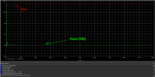
 on Webench is OK ...] that does not work ... I use the std biblio LM73606RNP_TRANS by default. It seems that there are two peaks on SW / CBOOT at 40us and then ... 0V definitively as if there is a problem of boot / init ... Please help me I cannot see any mistake as all the schematic is standard based ...


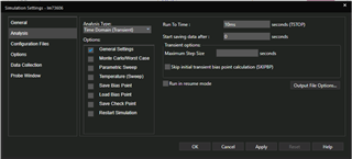 I used the default config profile.
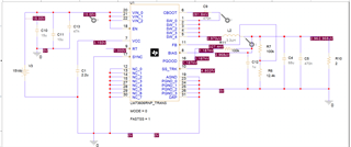
 for instance here the startup simu (10 min to finish it on my PC) But that does not do exactly what I want (this is 12V > 5V). Nevertheless I can keep it as a reference and slightly modify it until it fits as what I want ... So thank you for your support I will come back to you if I cannot do what I aim to. In a second time after I will finalize my design is it possible to make a review of my schematic by TI ? I also want to design a more complex stuff: TPS7H5007 + TPS7H6015 based, how can I do as it does not exist a complete TI simulation of both ICs together ? What do you advice to me for that design ?