


Tool/software:
I'm using the F280039C with the HW E6 version to test the PFC functionality in Lab 5. In the User Guide, it mentions:
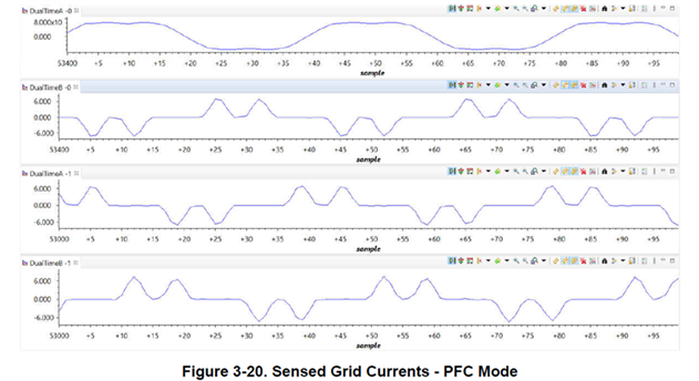
"Note the input current has a double bump without the neutral connected to the source at light load"
(as shown in Graph1)
However, in my actual test, after disconnecting the neutral and enabling the middle-point voltage control (TINV_MIDDLE_POINT_CONTROL_ENABLE), I still cannot observe the expected double-bump waveform. Instead, the input current shows irregular peak-to-peak values and noticeable distortion, as illustrated in Graph2. The waveform is unstable and does not resemble the example provided in the guide.
-
Yellow: Phase A line current
-
Green: VAB
-
Blue: DC link capacitor midpoint ripple
-
Red: Q2 PWM signal
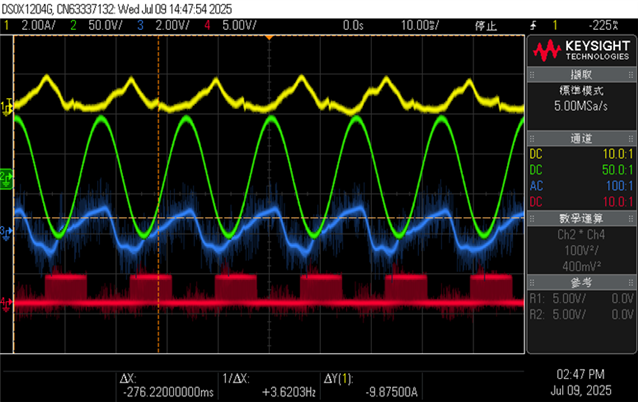
I have enabled the middle-point voltage control and disconnected the neutral from the grid. The PLL is also working, but the midpoint voltage seems to drift, which leads to distorted current waveforms.(Even when the middle point control is disabled, the current still shows severe distortion.)
Have you encountered a similar issue, or do you have any suggestions on how to stabilize the midpoint and improve current quality?