Part Number: TPS54KB20
Tool/software:
こんにちは。
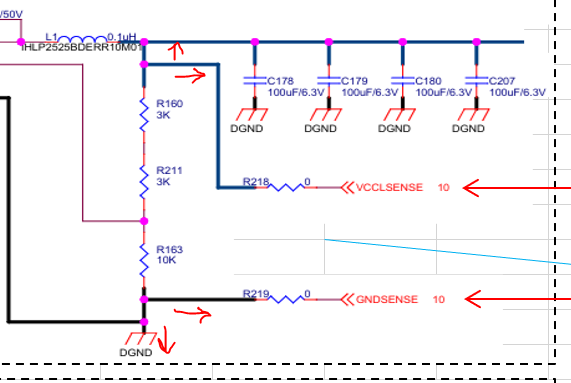
回路図とレイアウト ファイルを見て、コメントをお寄せいただけますか?
何か変更する必要がありますか?
(1)回路図
リモートセンスとFB信号の接続に問題はありませんか?
(2)PCBレイアウト
リモートセンスとFB周辺の部品配置やパターン接続は適切か?
よろしくお願いいたします。
layout20250722.zip
This thread has been locked.
If you have a related question, please click the "Ask a related question" button in the top right corner. The newly created question will be automatically linked to this question.
Part Number: TPS54KB20
Tool/software:
こんにちは。
回路図とレイアウト ファイルを見て、コメントをお寄せいただけますか?
何か変更する必要がありますか?
(1)回路図
リモートセンスとFB信号の接続に問題はありませんか?
(2)PCBレイアウト
リモートセンスとFB周辺の部品配置やパターン接続は適切か?
よろしくお願いいたします。
layout20250722.zip
Hi Takuya-san,
I reviewed the layout and identified issue with the layout.
Currently, the remote sense is connected to both the local and remote locations. This needs to be corrected so that the sense lines are connected only to either the remote sense or local point - not both.
If you intend to regulate based on the remote regulation point, you'll need to cut the traces (or insert series resistor as a placeholder) going to the local VOUT and DGND sensing lines.

Thank you,
Tomoya