This thread has been locked.

If you have a related question, please click the "Ask a related question" button in the top right corner. The newly created question will be automatically linked to this question.

TPS40304: VRM ESR and ESL Values

Part Number: TPS40304


Tool/software:

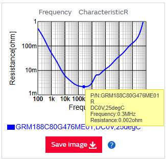
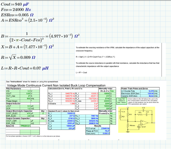
Hi, I am trying to do PDN analysis for TPS40304, I need the procedure to find VRM ESR and ESL if I used  2 (470uF) capacitors in parallel and 1 (300nH) Inductor. I am using it to convert from 3.3V to 0.85 V

  •   

    If your frequency of interest for your PDN is above the bandwidth of the TPS40304 controller loop (generally less than 100kHz for a 600kHz switching frequency) the ESR and ESL of the voltage regulator will be dominated by the output capacitors, and you can effectively ignore the VRM itself.

    If frequencies below the bandwidth of the control loop, the ESR/ESL of the converter will depend heavily on the control loop and it's gain. 

    Under Design and Development, Design Tools and simulation - https://www.ti.com/product/TPS40304#design-tools-simulation 

    there is a Type III Compensation Tool - https://www.ti.com/tool/download/SLUC263 

    You can enter your compensation components and output capacitors to evaluate the control loop versus frequency

    To estimate the sourcing resistance of the VRM, calculate the impedance of the output capacitors at the crossover frequency.

    R = Sqrt [ (1 / (2×Pi×Cout×Fco) )² + ( ESRco )² ] 

    To estimate the source inductance in parallel with that resistance, calculate the inductance that has that characteristic impedance with the output capacitance

    L = R² × Cout

  • Hi Peter,
    Thanks for the great support, the Pspice models I got from the website for TPS40304 is giving some errors, could you support us with a proper pspice model.

  •  

    What error is the model giving you?

  • TPS40304.lib(189): No such parameter defined.
    X_COMP_CALIB_CALIB_TIMING_U6         MENA COMP_CALIB_CALSIG one_shot PARAMS:  T={(1.1-SS)*1e6}

    TPS40304.lib(191): No such parameter defined.
    +  PARAMS: T={(0.8-(0.7*SS)) * 1e6}

    TPS40304.lib(154): No such parameter defined.
    C_PWMOSC_C1         PWMOSC_SRAMP 0  1n IC={SS}

  • If my ESR Value of the output capacitor is varying at higher frequencies how do I select a particular value

  • If my ESR Value of the output capacitor is varying at higher frequencies how do I select a particular value

    It is most common to select the ESR value at the bottom of the Resistance versus Frequency curve


  • 1. This is the error I am getting in the pspice model of TPS40304


    TPS40304.lib(189): No such parameter defined.
    X_COMP_CALIB_CALIB_TIMING_U6         MENA COMP_CALIB_CALSIG one_shot PARAMS:  T={(1.1-SS)*1e6}

    TPS40304.lib(191): No such parameter defined.
    +  PARAMS: T={(0.8-(0.7*SS)) * 1e6}

    TPS40304.lib(154): No such parameter defined.
    C_PWMOSC_C1         PWMOSC_SRAMP 0  1n IC={SS}


    2.I have calculated my ESL and ESL Values, I don't have any ceramic capacitors, I have only 2 electrolytic capacitors at the output.
    If my target frequency is 600KHz and the capacitors that I have used is

    T530X477M006ATE004

    Could you confirm If the ESR and ESL values that I got is correct? or any other suggestions?

  • 1. This is the error I am getting in the pspice model of TPS40304


    TPS40304.lib(189): No such parameter defined.
    X_COMP_CALIB_CALIB_TIMING_U6         MENA COMP_CALIB_CALSIG one_shot PARAMS:  T={(1.1-SS)*1e6}

    TPS40304.lib(191): No such parameter defined.
    +  PARAMS: T={(0.8-(0.7*SS)) * 1e6}

    TPS40304.lib(154): No such parameter defined.
    C_PWMOSC_C1         PWMOSC_SRAMP 0  1n IC={SS}

    I have passed this feedback to our modeling team to see if we can identify the issue.

    2.I have calculated my ESL and ESL Values, I don't have any ceramic capacitors, I have only 2 electrolytic capacitors at the output.

    Electrolytic capacitors tend to have high ESR and ESL, so the output voltage on switch mode BUCK converters with all electrolytic output capacitors tend to be noise, especially at high frequencies.  You might want to consider adding some ceramic capacitance to help reduce high-frequency noise.

    Could you confirm If the ESR and ESL values that I got is correct? or any other suggestions?

    According to the KEMIT datasheet, the ESR of the T530X477M006ATE004 is 4mΩ.  With 2 capacitors in parallel, the effective ESR would be 2mΩ against the total capacitance of 2× 470μF 

    A = 0.002 ^ 2 = 4^-6 

    B = 1 / (2 pi 940μF × 24kHz) ^ 2 = ( 0.007055 ) ^ 2  = 4.977 ×10^5 

    Sqrt (A + B) = 7.33mΩ 

    L = 0.00733^2 x 940μF = 50.50nH