This thread has been locked.

If you have a related question, please click the "Ask a related question" button in the top right corner. The newly created question will be automatically linked to this question.

LM5122: Optimizing an LM5122-Based Boost Converter: Achieving 5 V Startup and >400 mA Output

Part Number: LM5122

Tool/software:

Problem Overview

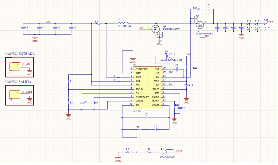
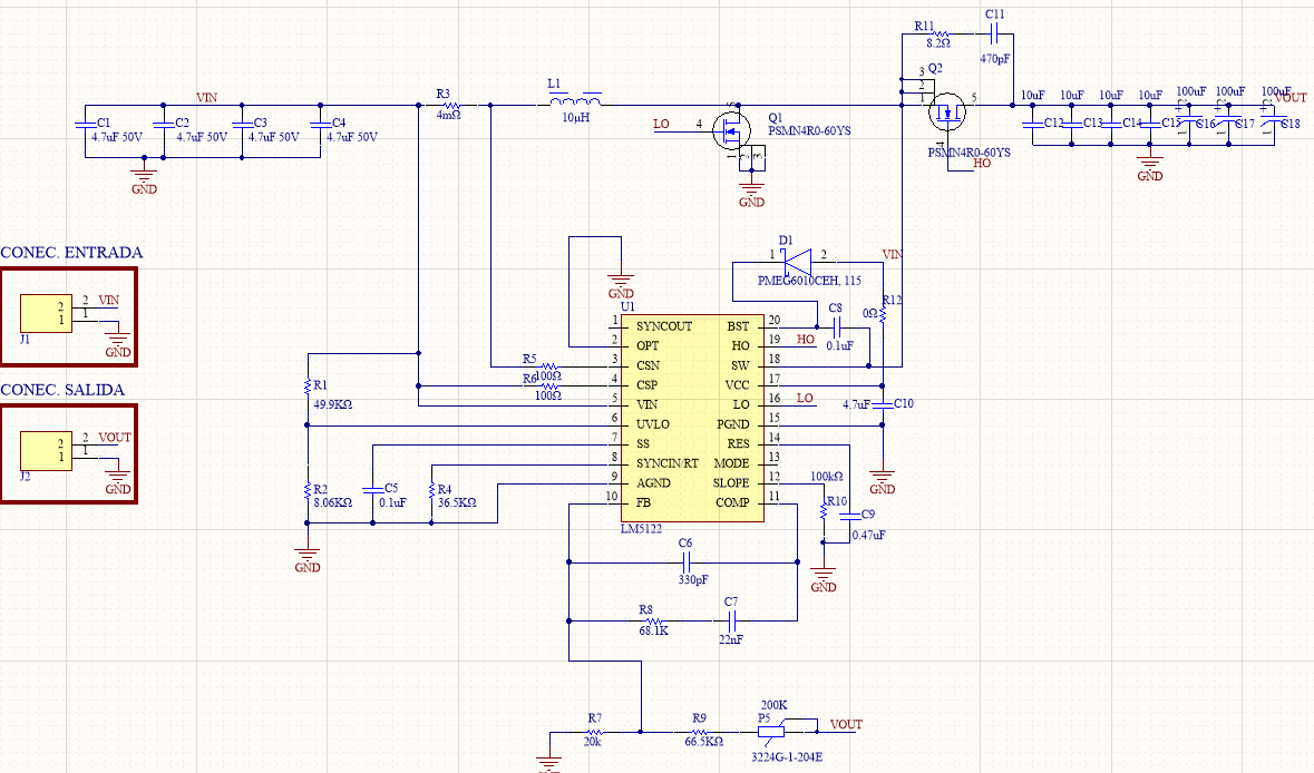
We have implemented a boost converter using the LM5122 controller, faithfully replicating the “Typical Application” from the datasheet. During bench testing, we’ve encountered two critical issues:

  1. Startup Below 9 V
    Although the datasheet specifies a minimum operating voltage of 3 V (4.5 V for startup), our design will not initiate switching below 9 V. While our target system normally provides ≥12 V, reliable operation from 5 V would greatly enhance versatility.

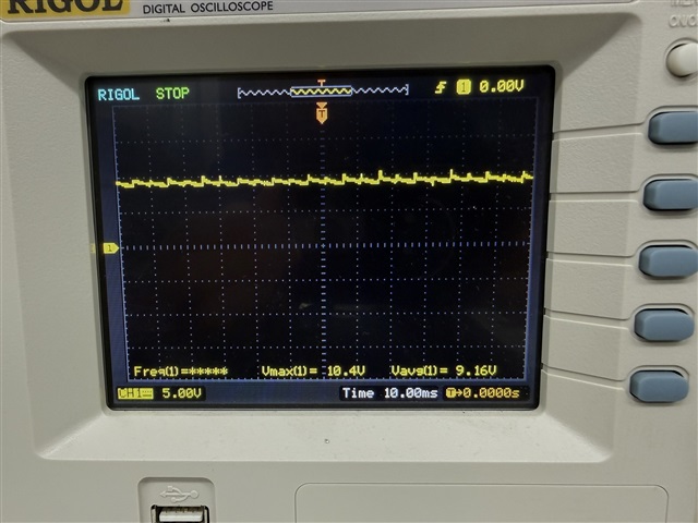
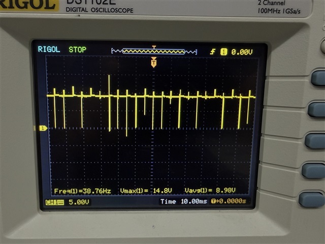
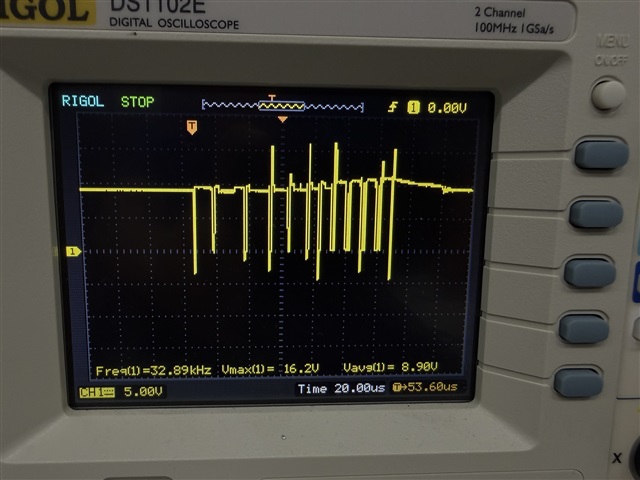
  2. Output Current Limited to ~400 mA
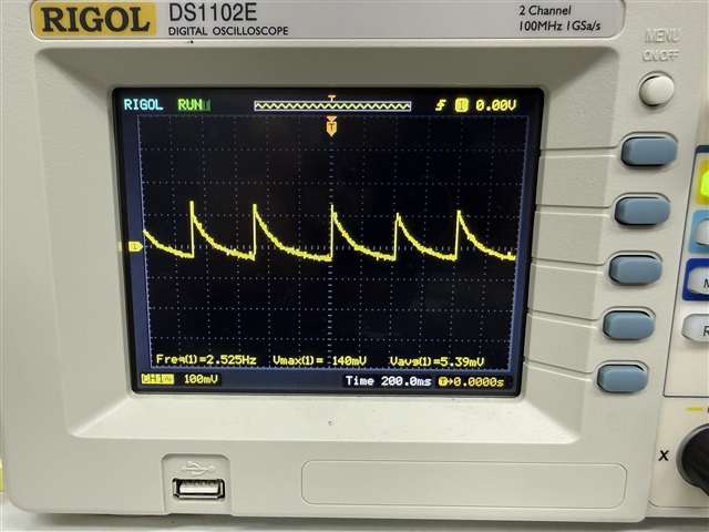
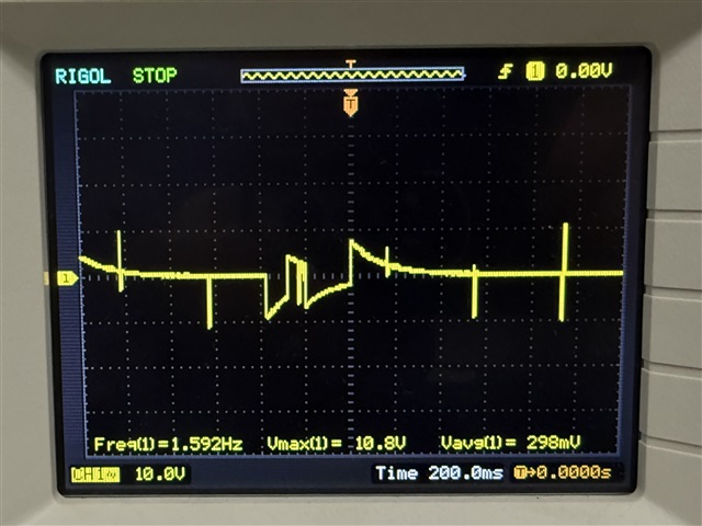
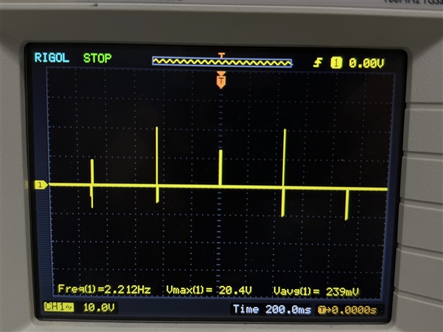
    Under loads exceeding 400 mA, the output voltage collapses to nearly the input level, and the device enters fault (short-circuit) blink mode. We have a 3 A current limit provision, so the converter should not be tripping at this low current level.

Questions & Requests for Advice

  • Has anyone achieved reliable 5 V startup with the LM5122? What adjustments to the start-up circuitry do you recommend?

  • How can we prevent the converter from entering fault mode when the load exceeds 400 mA?

  • Hi Pablo,

    Please share some waveforms when describing your issue.

    There is no value for the components in the schematic.

    What is the input and output voltage? What is the load current?

    Best Regards,

    Feng

  • Hi Feng,

    Thank you for your reply. Please find below some additional details and scope captures regarding our issue with the LM5122 boost design.

    Test conditions:

    • Input voltage: 12 V (tested also with lower voltages down to 5 V, no startup below ~9 V).

    • Target output voltage: 30 V.

    • Expected load current: up to 3 A, but the converter trips already above ~400 mA.

    Attached waveforms/photos:

    1. Vout ripple (AC-coupled) at 30 V output. Ripple does not look problematic.

    2. SW pin during abnormal behavior (strange switching pattern observed occurring at random times).

    3. SW pin under normal operation.

    4. Vout with a 300Ω load (expected ~30 V, but we only see ~10 V when load is connected). The main power supply current is only about ~5 mA, while it should be close to 350 mA

    5. SW pin with the load connected.

    6. Same as 5, but zoomed in when the switching occurs.

    Images 1,2,3 without load

    Images 4,5,6 with load

    Schematic:

    Questions & Requests for Advice

    • Has anyone achieved reliable 5 V startup with the LM5122? What adjustments to the start-up circuitry do you recommend?

    • How can we prevent the converter from entering fault mode when the load exceeds 400 mA?

    Any guidance on what to check or modify would be greatly appreciated.

    Best regards,
    Pablo

  • Hi Pablo,

    The UVLO setting in the schematic shows a startup voltage of 8.7V.

    Before operating down to 5V, it seems you FET is not suitable for 5V operation. Choose a logic level FET for 5V gate driver.

    Please start the design with LM5122 design calculator.

    Best Regards,

    Feng