Other Parts Discussed in Thread: TMS320F280049C
Tool/software:
Hi TI Team and Experts,
I’m designing a single-phase totem pole PFC circuit with the following specifications:
-
Input: 220VAC
-
Target Output: 400VDC
-
Power Rating: 7kW
-
Reference Design: PMP23338
-
Topology:
-
High-frequency switches: Four SiC MOSFETs (two pairs in parallel)
-
Low-frequency switches: Two SiC MOSFETs
-
-
Key Components:
-
Power inductor: 200 µH
-
Switching frequency: 65 kHz
-
I’ve imported the PMP23338 project into Code Composer Studio (CCS), but need assistance with three critical issues:
-
Parameter Adaptation:
How should I modify the project parameters (e.g., inductor value, switching frequency, MOSFET configuration, power stage scaling) to align with my 7kW custom design? -
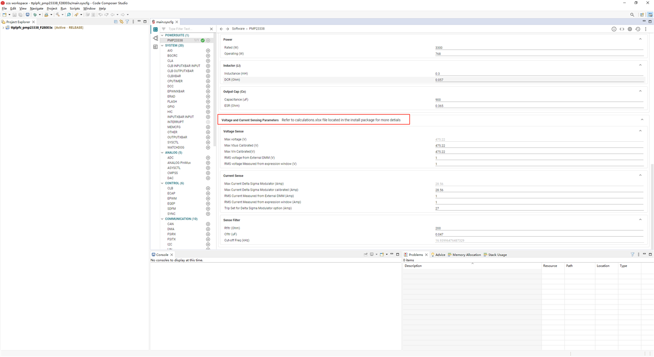
Configuration File Clarification:
I’m unable to fully interpret all parameters inmain.syscfg. Could you explain the purpose of key registers (e.g.,PWM,ADC, current/power limits, protection thresholds) relevant to high-power totem pole PFC control? -
Missing Design Documentation:
The reference design mentions acalculations.xlsxfile for scaling factors, but I cannot locate it in the PMP23338 package. Where can I access this?-
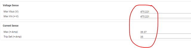
Note: My voltage/current sensing circuits have different scaling factors due to the 7kW power level, and I need to validate them.
-
Supporting Information:
-
Schematic and BOM are available upon request.
-
Controller: TMS320F280049C
-
Critical Design Challenge: Scaling PMP23338 (lower power) to 7kW with parallel SiC MOSFETs.
Thank you for your expertise!
Best regards,
Han.