This thread has been locked.

If you have a related question, please click the "Ask a related question" button in the top right corner. The newly created question will be automatically linked to this question.

PMP22087: HB LLC CONVERTER "TRANSFORMER" calculation

Part Number: PMP22087
Other Parts Discussed in Thread: UCC256404

Tool/software:

I am working on an LLC resonant converter design,
Lm=490µH,
Lr=90µH

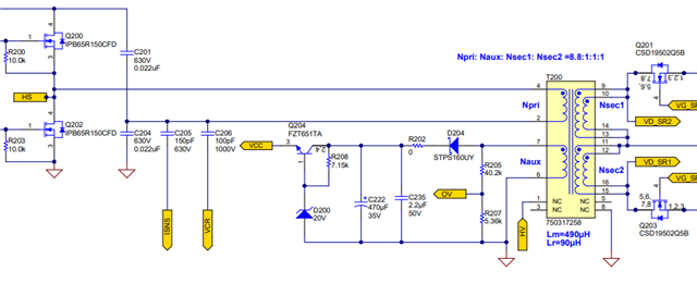
My next step is to design the transformer.Could someone explain:

  1. What type of transformer is typically used after the resonant tank circuit in an LLC converter (UCC256404)? 

  2. How are the transformer specifications determined (core type, turns ratio, winding details)?

  3. What calculations are required to ensure the transformer meets voltage, current, and isolation requirements?

  4. Are there any standard guidelines or reference methods for calculating turns, core selection, and wire sizing for LLC resonant converter transformers?

Any detailed explanation or reference material would be greatly appreciated.

Regards.

  • Hi Suman,

    My responses below:

    1. Transformer with Ferrite core material are typically used to form LLC resonant inductors.

    2. You can first follow the flow chart (Figure 14) in the PSDS paper: Designing an LLC Resonant Half-Bridge Power Converter: https://www.ti.com/seclit/ml/slup263/slup263.pdf . Once turns ratio and resonant tank parameters are determined, you can than find a proper core size and shape for vendor (eg. TDK, DMEGC, Ferroxcube...) soft ferrites catalog to find out a core that meets your needs. In normal operation, we usually keep Ferrite core to operate at ~50mT.  

    3. We usually need to follow safety standards. Depends on your application, required standard could be different.

    4. PSDS paper mention above should be your good first step for LLC design. 

  • Thank you sir  
    I have encountered a few issues:

    1. In the above schematic, there is no resonant capacitor (Cr) and (Lm) shown.

      • Should this capacitor be placed in series or in parallel within the resonant tank?

    2. I also need to design an auxiliary winding for the LLC converter like the schematic.

      • How should I calculate the number of turns and design parameters for this auxiliary winding?

      • Are there specific guidelines to ensure proper voltage levels and isolation for auxiliary supplies?

    Any detailed explanation, design formulas, or reference material would be greatly appreciated.


    Regards