This thread has been locked.

If you have a related question, please click the "Ask a related question" button in the top right corner. The newly created question will be automatically linked to this question.

LM5149-Q1EVM-400: Thermal Issue

Part Number: LM5149-Q1EVM-400
Other Parts Discussed in Thread: LM5149, LM5148, LM5149-Q1

Tool/software:

Hi, 

I just received a fresh EVM today and performed a simple test. The board was powered with a typical input voltage of 48 V and gradually loaded up to 8 A using an electronic load, tested in an open area.

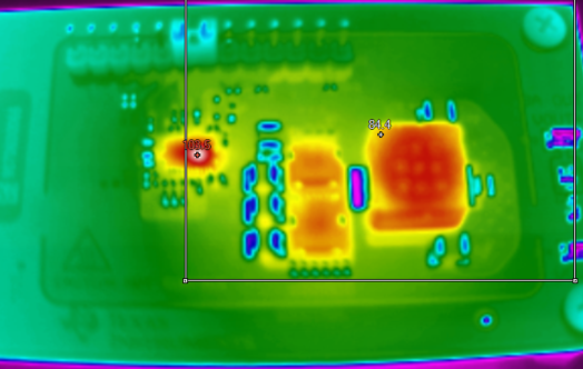
I noticed that the IC temperature rises significantly higher than other power components such as the inductor and MOSFET. No configuration changes were made—the setup was simply input wiring, power supply, and load connection.

Temperature data of my measurement: 

Data obtained from TI evm datasheet 

As an additional note: from TI’s documentation, the LM5148 is a similar device with comparable performance and is pin-to-pin compatible with the LM5149 on this EVM. When we swapped in the LM5148 under the same loading conditions, the IC temperature was noticeably lower compared to the LM5149.

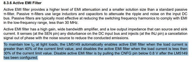
Has anyone else encountered this behavior of LM5149? Could there be a setup detail or characteristic of the LM5149 that explains the higher temperature rise? Is there any reason behind for the IC temperature issue?

Thanks in advance for your insights.

  • Hi Yong,

    The LM5149 is simlar to the LM5148, but it has AEF (active EMI filter) that is powered from VCC. I can only surmise that this is what's causing the higher IC temperature.

    Regards,

    Tim

  • Measuring the voltage drop on R6 (the path from VCC to AEFVDDA) gives the AEF current consumption.

    It's possible to connect an external 5V source to VCCX at the header on the EVM to provide the VCC bias current. This will reduce the VCC subregulator dissipation where the bias current is derived from VIN in the existing setup.

    Another option is to connect a 6.8V Zener from VOUT to VCCX, thus dropping the voltage from 12V to 5.2V. Note that VCCX accepts a voltage from 4.3V (the VCCX changeover threshold) to 5.5V (the max operating spec).

    --

    Tim

  • Hi TI team,

    I have similar observations. When tested in the exact same conditions, fresh-out-of-box evaluation module did not have similar temperature profile as presented in the user's guide.

    LM5149-Q1 Buck Controller Evalulation Module User's Guide

    VIN = 48 V, IOUT = 8 A, Tamb = 25°C, No Airflow

    The temperature of LM5149 controller IC is at ~100°C, even higher than the inductor temperature. Whereas "Marker 4" on Figure 6-14 in the User's Guide only shows 68°C. I understand the heat dissipation could be attributed to the AEF feature of LM5149. However, the large temperature discrepancy between our physical evaluation module and the user's guide report is perplexing. Could the AEF be driving so hard to silence noise from the input voltage source?

    Furthermore, if LM5149 is designed into a product that operates in higher ambient temperature, it would easily hit the thermal shutdown threshold of 175°C. I understand the AEF can be disabled by pulling the CNFG pin below 0.8 V after LM5149 start-up and configured, but this requires additional logic circuits. Is there any way to completely disable AEF on LM5149 by disconnecting the pins INJ, SENSE, REFAGND, or the only feasible way is to use LM5148?

  • Hi Kai Wei,

    The AEF current consumption from VIN is dissipative. How is the IC at light load when AEF is not operating? 5V external VCC (connected to VCCX) is almost mandatory for AEF applications when running off of a 48V input.

    Regards,

    Tim

  • From the data sheet: "Disable active EMI filter is by pulling the CNFG pin below 0.8V after the LM5149-Q1 has been configured." If AEF is not required, then the LM5148 is the best choice.