


Other Parts Discussed in Thread: LMK04828
Tool/software:
Hi everyone!
In the document High-Channel-Count JESD204B Clock Generation Reference Design for RADAR and 5G Wireless Testers there is an example with not-very-detailed description of steps. I would like to repeat that example on my setup that is very close to TIDA-01023 reference design: multiple slave LMK04828 are driven from master LMK04828 with CLKin0 and CLKin1 inputs. CLKin1 is 300 MHz and CLKin0 is divider reset signal.
Am I right in my assumptions of how is it done there:
1) Configure slave devices in distribution mode with CLKin1 used as clock distribution chain input and CLKin0 is bypassed into SYSREF/SYNC path:
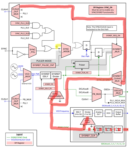
2) Configure master in distribution mode with CLKin1 routed into clk dist path and Pulser routed to SYSREF path. SYSREF divider is also reseted during sync:
3) send an SYNC event via SPI, so Pulser generates N pulses and thus aligns all outputs of master LMK04828
4) disable synchronization of dividers on master device, and enable CLK outputs by setting 0 to correspondind CLKout_X_(X+1)_PD bits. Now all slaves are clocked with 300 MHz high-speed clk
5) send an SYNC event via SPI, so Pulser generates N pulses and thus aligns all dividers of slave LMK04828 devices
6) each slave device changes SYSREF mux input to continuous and now outputs high-speed clk signals aligned with SYSREF singal, and all slave devices have deterministic delays to each other.