TIDA-01187: OPA2356

Part Number: TIDA-01187
Other Parts Discussed in Thread: OPA2356, THS4541, OPA857

Tool/software:

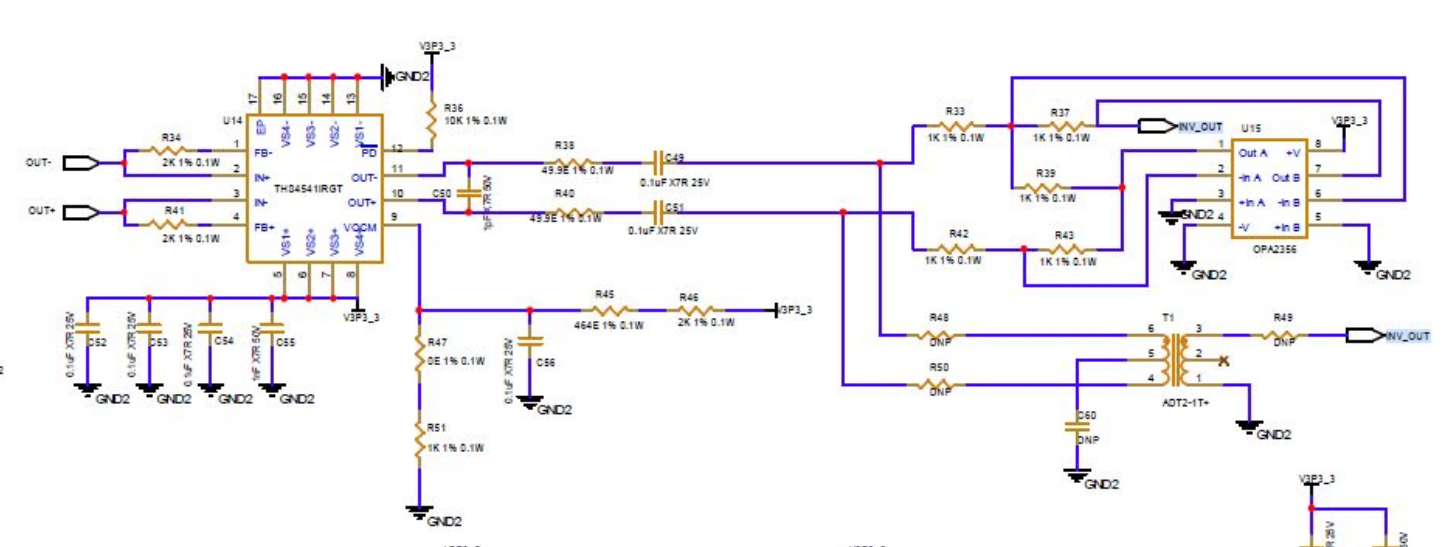
This question is releated to

 TIDA-01187: Schemati Review of TIDA-01187 based design, using THS4541 as single ended output 

I exactly used same schematic and realised my board now but unforutunately i am not able to see the output as expected from OPA2356, why so ?

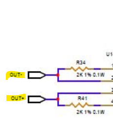
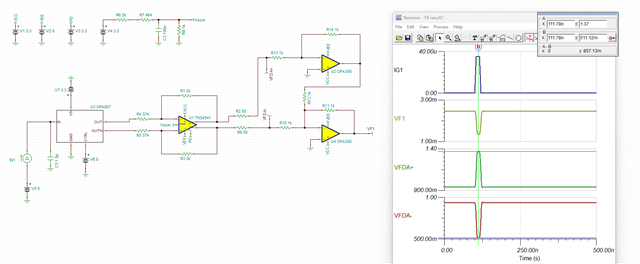
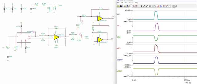
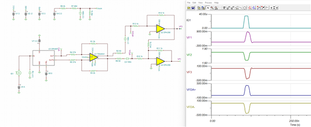
Below the problamatic portion , my doubt is with the coupling between THS4541 and OPA2356

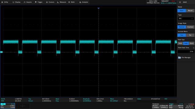
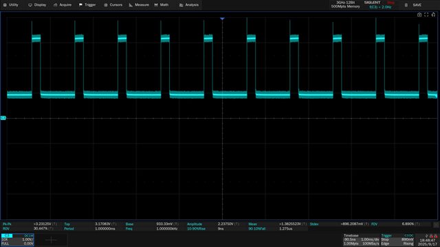
Update : I have seen output from post capacitor C49 and C51 on oscilloscope, the pulse shape detoriates after this else the output wafeform is perfect across C50, which i feel is the culprit, can i remove the 49.9E and 0.1uF Cap and short the path ? i feel that should solve the problem, or is there any better alternative ? is DC coupling required for differential to single ended conversion path that is before OPA2356, please suggest.

  • Hello Shyam,

      Yes, you are correct the issue is the AC coupling capacitor. The reason why is because the OPA2356 is used in single-supply configuration, if it was used in split-supply configuration it would have worked. DC coupling is not required for differential to single ended conversion path in the usual sense, but since OPA2356 is used in 3.3V single supply, it will need a DC voltage to bias the voltage since it will saturate and not function properly if the common-mode is at 0V. 

       Another method is to keep AC coupling capacitor, then add a voltage bias at +IN pin of the amplifier, but above would be the best action to take for an easy fix. 

    Thank you,
    Sima 

  • Thanks for your response

    My Vcm is 1V

    I remove the 1p Cap inbetween the output terminals of THS and below is the output voltage

    At -Ve Terminal

    At +Ve Terminal

    If i see the output on +ve terminal is double the -ve terminal, i am not sure of reasons

    i dont see any output at the output of OPA

    I tried removing coupling caps and shorted the pads, the output is nothing,

    i tried the coupling caps to remain 0.1uF, at that setting the output comes only for optical pulse width of 200nS and less and if PW is increased the output goes OFF.

    for above setting the output is only a 20nS pulse.

    Kindly throw some light on where exactly i am going wrong

    where as in simulation removing coupling caps also makes output to disappear

    i strictly trusted simulation and put 49.9ohm in series with 0.1uF , but in reality output is nothing

    so the coupling caps may not be the issue and the issue is something else.

  • Hello Shyam,

      Thank you for the additional details, yes it looks like something else is off due to the double output.

      Above scope shots are from VOUT+ and VOUT - after removing C50 from the schematic. Can you also provide the scope shots from OUT- and OUT+ nodes?

    Thank you,
    Sima

  • i dont have a scope shot now, but i can say, the output is as per simulation only

    on OUT+ the swing is in mV and on OUT- the swing is almost 1V i think, the input is from TIA OPA857

    i dont think there is a problem there.

    do you want any other scope shots ?

  • Hello Shyam,

      Is below the correct configuration that you have set up on your board?

       The FDA is setting the output common-mode voltage at around 0.94V. This output voltage will become negative at the output of the amplifier. And if add back in the AC coupling capacitors, it will be as shown below which is a negative input to the amplifier which will violate both input and output of the amplifier.

       Unfortunately, the only solution to fix this is to use split supply on your difference amplifier, for input source above this will be 3V to -2V supply. Or add a voltage bias to VIN+ pin of both the amplifiers. 

       I know this is not possible for you, and apologize for the inconvenience this has caused. I will do a redesign and we can probably eliminate the FDA and use a single channel difference amplifier from the OPA857 to the comparator. I will be working on a redesign, and will update you by Monday. Let me know if this redesign direction is feasible for you.

    Thank you,
    Sima

  • Why cant i tie directly THS output to my comparator, where Vref i can put arround 1V+ ?