This thread has been locked.

If you have a related question, please click the "Ask a related question" button in the top right corner. The newly created question will be automatically linked to this question.

DRV3946-Q1EVM-DESIGN: Driver GUI

Part Number: DRV3946-Q1EVM-DESIGN

Hello, 

We recieved a evaluation board and intended to use it to control a contactor. I have 2 questions. 

  1. Does the board automatically have flashed software or do we need to flash it ourselves?c
  2. When we connected the board to the GUI and to a 12V power supply to control a contactor on the output ports, we were able to see the GUi and the device communication but when we enabled the Driver and Output 1 the contactor did not close. We have been trying to troubleshoot this issue, originally we thought it was the software but after looking at the user guide it is not clear if it is software or hardware. There are many headers and jumpers along with the GUI having many options for resistance, KHz, ect. I was hoping you could help us with the trouble shooting process. 

If the board was not already flashed then that may be the issue for the GUI. If it was then we need to take a further step into troubleshooting and determine the cause for the signal not being sent correctly. We did use an ocilliscope to see if the voltage was being outputed and it was indeed showing but with no current. 

Hopefully you can help, 
Thank you. 


  • Hello Landon,

    Thanks for your question and here are my comments

    1. The board comes with a F/W flashed. There is an option to flash the latest F/W through GUI this can be done once to ensure the latest version is in the board (The procedure can be seen in the users guide for this)

    2. Couple of questions on this

    • I am assuming that the default configuration of jumpers are not changed, can you provide a picture of the board to see what is the jumper settings.
    • Can you confirm which all registers are already written. You can give me a screenshot of the GUI to be able to see what is happening.
    • Are you able to read out the Status registers? If so please let me know the read outs.

    Thanks,

    Ibinu

  • This is the board. I cannot get the GUI screenshot yet, I will follow up with that on Monday. 

  • Thanks Landon.

    From the image, looks like there is a jumper not put in. Cannot clearly see which one. It will be good to add that also(I am assuming you are checking Channel A)

    Looking forward to the GUI images also.

    Thanks,

    Ibinu

  • Hello, I am still working on getting the GUI back up and running, we had to reinstall everything on the laptop. Now it will not register the TI Cloud Agent. When I get it running I will send you a screenshot of it. 

    Thank you, 

    Landon.

  • Thanks Landon. I will wait for your confirmation and provide further debug steps if necessary.

  • Here is the GUI, we were wondering about the NAD setting/ nfault/NAD resistor. That also is the jumper that is missing, so this could be the issue. When I enable #1 on driver A nothing happens. It is supposed to close the contactor as it would send the current to that output. We were also wondering about the resistor values and the peak and hold current, they seem to be directly tied to the RIPROPI. 

    If you could explain some of these that would be much appreciated, Thank you. 

  • Thanks for sending me the screenshots.

    From this i feel the power up of the DRV3946 is not complete. All registers are reading 0xFF, this could mean that there is one the following errors - VDD_ERR, NAD_ERR or DEV_ERR. 

    We can debug the following 

    1. Do you see the nFAULT pin also going LOW? 

    2. Is the 5V and 12V coming correctly (This can gate the power up if the voltages are not correct)

    3. I also noticed that the F/W version of the board is incorrect, (should not matter for this problem). But you can update that by clicking File  > Program Device.

    Thanks,

    Ibinu 

  • OK we fixed the errors on the GUI, driver B reads 2.1V, driver A 11.4V. There is a fault on driver A. nFAULT A is going low as well. Along with this we did add the jumper on the pins where it was missing. 

    Thank you, 

    Landon. 

  • Hi Landon,

    This is very good progress. I am able to see communication to be up.

    However, the GUI front panel does not look correct. 

    Can you help me with 2 things

    1. Please let me know what is the top side marking on the device

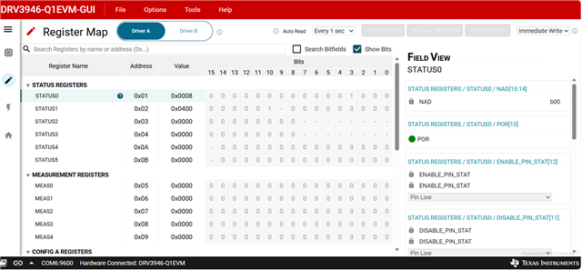
    2. Can you goto register page and let me know what the status register reads are(Screenshot of the register page would be good)

    Thanks,

    Ibinu

  • Ok this is how the GUI looks as of right now. 

    Which marking are you looking for? 

  • Hi Landon,

    This screenshot clears up my doubts.

    Looks like you have an earlier version of silicon (pre-production version). The Device_ID in status 1 is showing as b01. The final version has b10.

    I have reached out to the FAE supporting to get a new EVM.

    Thanks,

    Ibinu