


Part Number: TMS570LS0714
Hello TI Support Team,
I am currently working on boot code development for the **TMS5700714APZQQ1** device.
As discussed previously, I installed older version of Code Composer Studio and I am able to select the **TMS570LS0714** device in CCS while creating the project.
I created a test project for the **TMS5700714APZQQ1** device to verify boot code execution. For this verification I am attempting to toggle two GPIO signals.
The pins used in the test are:
READY → Pin 19 (N2HET1[0])
ACK → Pin 22 (N2HET1[2])
The following pins are used as data pins in our programming:
DATA → Pins 1, 2, 5, 8, 9, 10, 12, 18
Development workflow:
1. Created the project in Code Composer Studio.
2. Built the project successfully.
3. Generated the .S19 file.
4. Converted the .S19 file into a boot code array using our in-house tool (BPM Microsystems programmer environment).
5. The boot code is uploaded to RAM through the debug interface.
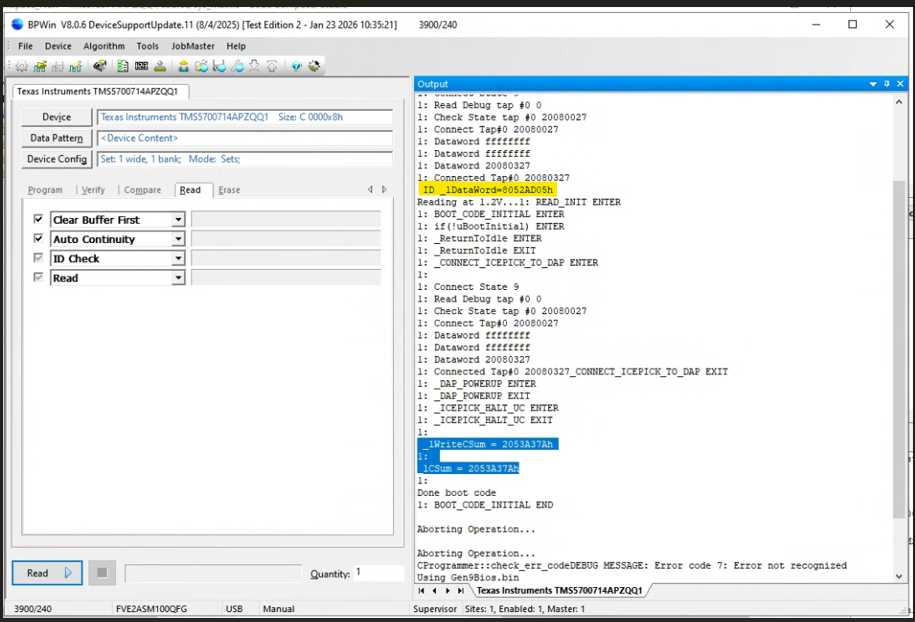
From the debug logs, the boot code write operation appears successful. The checksum verification matches:
_lWriteCSum == _lCSum
This indicates the boot code is being correctly written to the target memory.
For debugging purposes, I created a simple application that toggles the READY and ACK pins continuously. However, when observing the signals on the logic analyzer, I only see a single toggle instead of continuous toggling.
Current observation:
• Boot code upload appears successful, Checksum verification passes
• However, the GPIO pins do not toggle continuously as expected.
Any guidance or example projects for running simple GPIO toggle code on this device would be greatly appreciated.
Thank you for your assistance. I will attach few Screen shorts of observations
Best regards,
Rushikesh Porwal

