This thread has been locked.

If you have a related question, please click the "Ask a related question" button in the top right corner. The newly created question will be automatically linked to this question.

MSPM0G3519: XDS110 Debug probe AUX UART connection fail

Part Number: MSPM0G3519
Other Parts Discussed in Thread: LP-MSPM0G3507, MSPM0G3507

Greetings, 
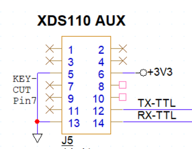
image.png

Given the above pinout, I need a sanity check and possibly warranty replacement ASAP!!!  The Rx and Tx are:

        .rxPin         = IOMUX_PINCM22,  // PA11
        .txPin         = IOMUX_PINCM21,  // PA10
 
passed through 10 Ohm resistors (noise and minimal protection to MCU pins)

I spent a few frustrating days trying to figure out why a ported application (from LP-MSPM0G3507 >> proprietary board with MSPM0G3519 ) wasn't communicating correctly.   I can step through debugging and see that my FreeRTOS tasks are running- LEDs and buttons trigger- but the debugging messages weren't getting sent to the Application/User UART.  After a few minutes, the XDS110 would disconnect altogether, but LED indicated application was still alive.

I just gave in and fired up the scope (the design was OK before, what could be wrong)?

I verified there is Tx data... Next, I plugged in the XDS110 AUX cable and the signal became corrupted.  The MCU couldn't pull the below 3V and not able to drive a true low.  I Disconnected the Aux cable connection and the RS232 Tx signal swing returned to 0V>3.3VDC.

This is the first we've used TI and this debug probe.  Up until now we were developing on the LP-MSPM0G3507 with almost exact I/O circuits without issue.

Is there additional circuitry needed to use the back channel UART? Configuration in the ccxml?

Please expedite this, as we've lost a lot of time in porting our design.


  • Hi Ken,

    The issue you are describing—where the signal is "corrupted" and cannot pull below 3V when the XDS110 AUX cable is connected—strongly suggests a voltage reference mismatch or a missing target voltage sense connection on the probe side. Couple things to check:

    1. You must connect Pin 1 (TGTVDD) of the 14-pin AUX connector to your target's 3.3V rail. Even if you are powering the board independently, the XDS110 must sense that voltage to match its logic levels.
    2. Ensure your AUX cable connections match the XDS110's specific UART mapping. The XDS110 Class Application/User UART is routed as follows on the 14-pin AUX header:
      • Pin 1: TGTVDD (Target Voltage Sense) — Required
      • Pin 3: Target TX (Connect to your MCU PA10/TX)
      • Pin 4: Target RX (Connect to your MCU PA11/RX)
      • Pin 2: GND (Ensure a common ground between the probe and your board)

    The reason your XDS110 disconnects entirely after a few minutes is likely related to the UART transfers corrupting the debug session. When the signal levels are marginal (like your 3V floor), the resulting electrical noise or ground loops can cause the XDS110's internal controller to reset or drop the USB connection. I would also recommend to check the 10Ω resistor. While fine for protection, ensure it isn't forming a voltage divider with a high-impedance internal pull-up in the XDS110 if the TGTVDD is missing.

    -Brian

  • Our pin assignment is copied from the XDS110 manual (SPRUI94).  The schematic snippet is at the top of this thread.

    I will add a jumper to TGTSUPPLYIN from 3.3V and see if that helps.

  • I connected target voltage to TGTSUPPLYIN, and this did not change the behavior.

    Question- Are the UARTTX and UARTRX labels with respect to my MSPM0G3519, or relative to the MSP inside the XDS probe?

  • Since you are only seeing this after switching from the LP to another board, I would try swapping these as you stated just to make sure there isn't some cross-over going on anywhere. Since you are seeing TX data, this may be as simple as swapping the two, but I recommend looking at the schematic from the MSPM0G3507 just to verify that all the necessary components are there and connected properly (aside from using the 14-pin connector).