UCC25800-Q1: Power Loss Calculation

Part Number: UCC25800-Q1
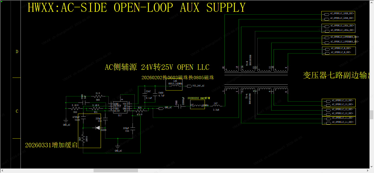
image.png

Hi, TI college

Here is our product using the UCC25800-q1 circuit electrical diagram.

Now, we wonder the Power Loss of this circuit working on this condition. 

Can you provide some accurate ways to calculate power losses. 

IF you have any questions about the working condition, it's fine to ask for more information!

  • Also, I want to know the Efficiency of chip especially the output of the chip connecting the transformer primary side.

    Thanks for your reply!

  • Hi

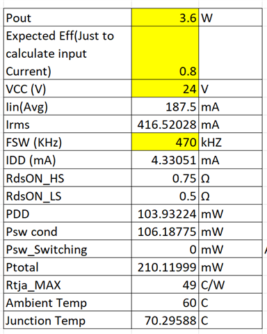
    Can you please share Total output power requirement, Input Voltage and switching frequency, I will share loss value.

    Other ways is to use this curve to get bias loss


    Then use Rds on value of top and bottom FET to get conduction loss, Assuming ZVS we can take Zero switching loss.


    These 2 can give you total loss in IC.

    Regards

  • Hi, 

    Our Total output power requirement is 3.6w, Input Voltage is 24V  and switching frequency is 470kHZ

    Can you provide a curve about current and frequency working on input voltage is 24V?

    Regards.

  • Hi

    Loss in IC will be ~ 210mW (Assumption you have ZVS on Switches) and temperature rise will be 10 Deg C from Ambient. Also losses on transformer are not included in this and needs to be calculated separately based on Rac of primary and secondary at 470kHz and current through each winding. 

    Regards