


Part Number: LM5171-Q1
Other Parts Discussed in Thread: LM5171
Hi, TI team
We use LM5171QPHPRQ1 designed12V-24V bidirectional DCDC. Now we found some issues during debugging:
- Could you help check the parameter selection is correct for current loop compensation, boost voltage loop compensation, buck voltage loop compensation that in attached LM5171_Buck_or_Boost_Quickstart_Tool_1.0.3_12V_24V? I have filled other basic parameters for our system design.
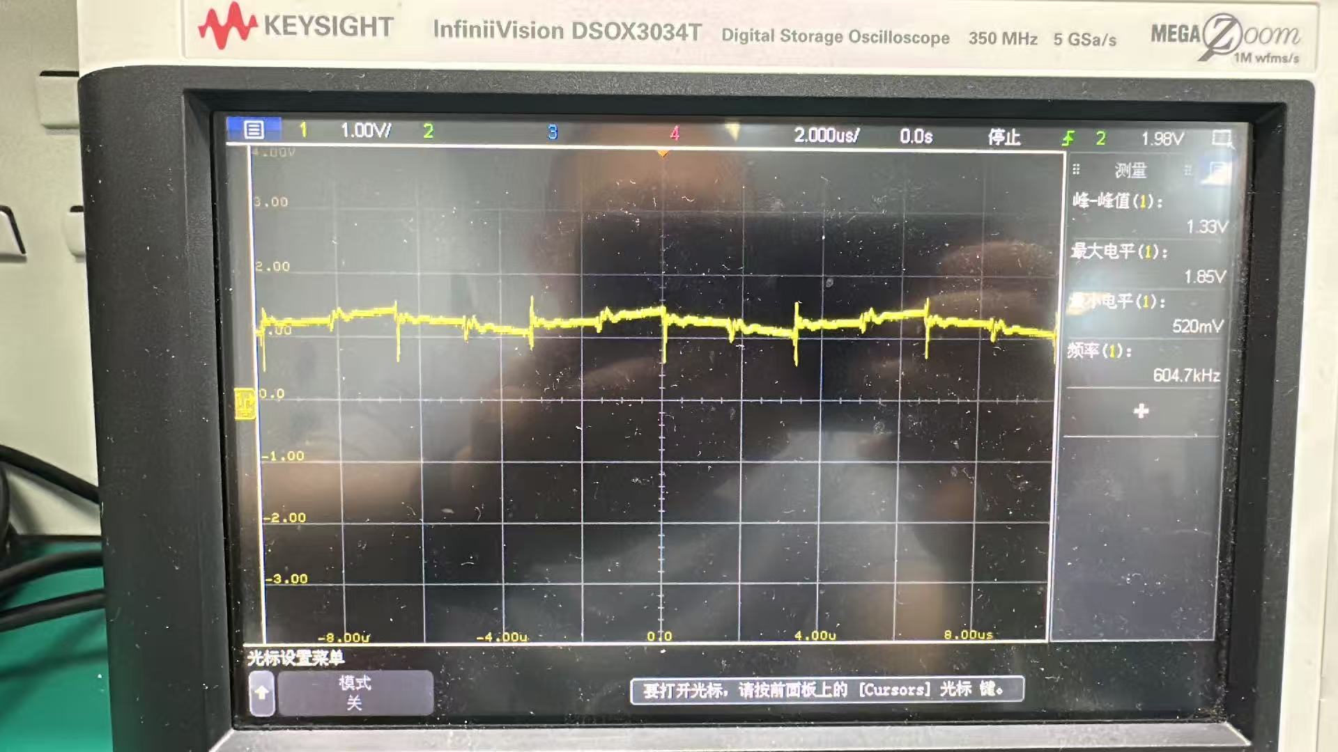
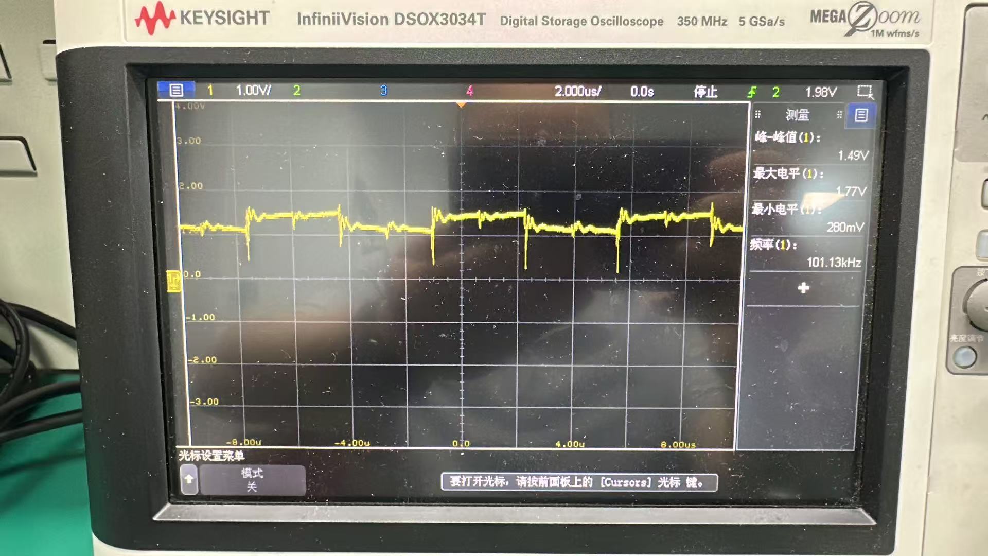
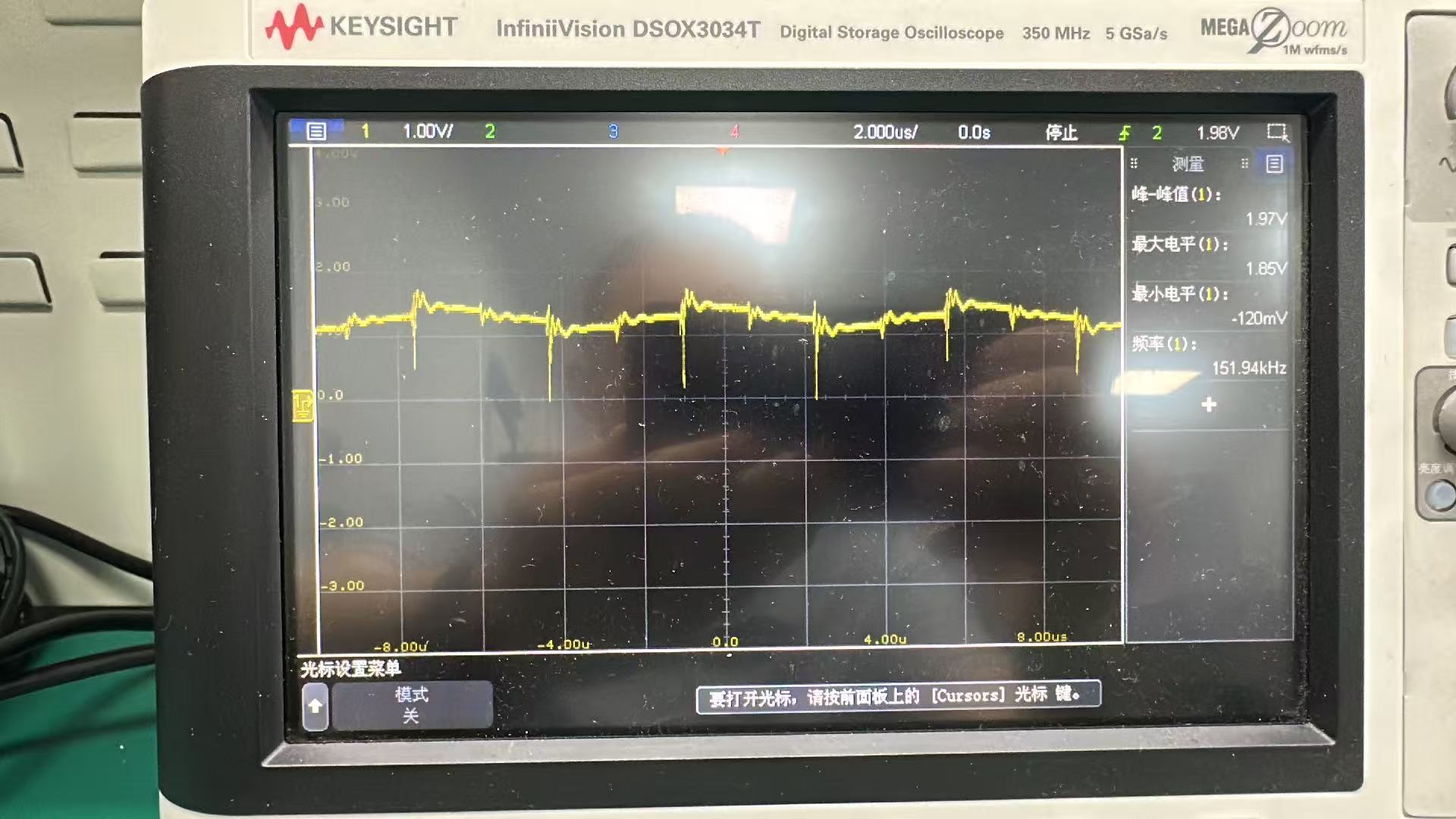
I used the components that calculated in the table, and measurement the COMP1, COMP2, COMP3, COMP4, FBHV wave as attached when in boost mode, We can clearly observe that these test points have distinct pulse spikes. I set DEM mode and no load in 24V side, the almost identical waveforms occur in the DEM mode and 1A load. Could you please help analyze this situation? How should I modify the compensation circuit, or the circuits of the power supply and the load side?
- We also found that BOOT_UV fault always report from I2C communication in boost mode. Have you ever encountered a similar situation? Is it related to CBT capacitors?

Note: Ignoring the parameters of the compensation circuit in the attached schematic, I conducted the tests based on the component parameters listed in the attached LM5171_Buck_or_Boost_Quickstart_Tool_1.0.3_12V_24V.
Could you please help analyze the fault and give us some suggestions for compensation components parameters adjustment?
Thanks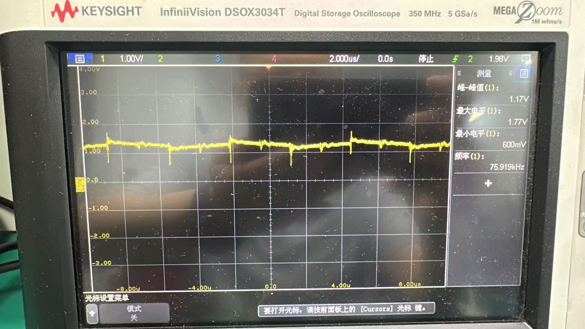
 LM5171_Buck_or_Boost_Quickstart_Tool_1.0.3_12V_24V.xlsx
