Part Number: TMDSEMU200-U
Hello,
Part Number: TMDSEMU200-U
Hello,
Hi Vilceanu,
Yes, this is a known issue. Your XDS200 most likely has outdated firmware that is incompatible with your CCS version. The fact that Windows detects the CDC ports but CCS "Test Connection" fails is the classic symptom — the USB interface works, but the debug protocol communication fails due to a firmware mismatch [1].
Since your XDS110 works with the identical setup (same adapter, cable, target), this confirms the problem is isolated to the XDS200 probe itself — not your adapter, cable, or target board.
The XDS200 requires firmware version 1.0.0.9 to work with modern CCS versions. Older firmware (e.g., 1.0.0.5) will cause exactly the behavior you're seeing [1]. The automatic update mechanism in CCS often fails, so a manual update is needed [2].
Step 1 — Check current firmware version:
Open a Command Prompt and navigate to your CCS installation's utility directory:
Step 2 — Update firmware (run in exact order):
Step 3 — Verify:
Confirm the output shows fwRev = 1.0.0.9 and cpldRev = 1 [1].
If your "CCS 2020" is actually CCS v11.1, there's a separate known bug (EXT_EP-10638) where the XDS200 can pass "Test Connection" but then fail to load programs. The workaround is to set symbol_loader=1 in the Expressions view after connecting [3]. This was fixed in CCS v11.2.
|
Check
|
Action
|
|---|---|
|
Firmware version
|
Run
xds2xx_conf get xds2xxu 0 |
|
Update firmware
|
Flash v1009 bin + CPLD files
|
|
Hardware issue?
|
Unlikely — CDC detection confirms USB HW is fine
|
|
Adapter issue?
|
Ruled out — XDS110 works with same adapter
|
To help refine this recommendation, it would be helpful to know:
Best Regards,
Zackary Fleenor
Hello Fleenor,
Thank you for your response and recomandations.
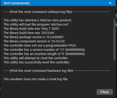
I have checkd the firmware version and it is 1.0.0.9, so the firmware is most likely not the cause of the issue.


3. I am using a standalone TMDSEMU200-U probe.
4.It is a custom board for the AWR2x44P.
BR,
Mihaela
Hi Mihaela,
Since the firmware is confirmed at version 1.0.0.9, we can rule out the firmware mismatch as the cause. Because the XDS110 works with the same hardware setup, the physical layer (cables, adapter, and target power) is functional. The issue is likely isolated to the software configuration or signal integrity at higher speeds.
Please perform the following steps to narrow down the cause:
1. Analyze the Error Log
The specific error message provided in your attachment is the most important diagnostic data point. Please confirm if the error indicates a USB/Driver failure (e.g., Error -1000) or a JTAG/Target failure (e.g., Error -245).
2. Verify Target Configuration (.ccxml)
Ensure that the Target Configuration file being used is explicitly configured for the XDS200.
3. Reduce JTAG Clock Frequency
The XDS200 operates at significantly higher speeds than the XDS110. On custom boards, high-speed JTAG signals can encounter signal integrity issues (impedance mismatches or crosstalk) that the slower XDS110 avoids.
4. Clarification on CCS Version
The version number provided (20.2.0.12) does not match standard TI CCS versioning (which is currently in the v12.x range). Please confirm if you are using a specialized toolchain or a specific SDK-integrated version of CCS, as this may affect driver compatibility.
Summary of required information for next steps:
Best Regards,
Zackary Fleenor
Hi,
Thank you for your guidance. Please find below the requested information and test results:
1. Error Log Analysis
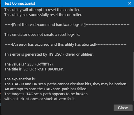
The error code I am receiving is:
Error -233 (0xffffff17) - please see the next screenshot

2. Target Configuration (.ccxml)
The target configuration has been verified with the following settings:
I also ran “Test Connection” from the Target Configuration editor.
The failure occurs during the connection process (consistent with the -233 error), suggesting an issue in JTAG communication.
3. JTAG Clock Frequency Test
I attempted reducing the JTAG TCLK frequency as suggested:
The connection issue still persists at both lower frequencies, so it does not appear to be related to signal integrity at higher speeds.
4. CCS Version Clarification
Hi Mihaela,
Thank you for providing the detailed screenshots and test results. The error code and your test results now give us a much clearer picture.
The error -233 (SC_ERR_PATH_BROKEN) with title SC_ERR_PATH_BROKEN has a specific meaning:
"The JTAG IR and DR scan-paths cannot circulate bits, they may be broken. An attempt to scan the JTAG scan-path has failed. The target's JTAG scan-path appears to be broken with a stuck-at-ones or stuck-at-zero fault."
This error means the emulator itself is communicating correctly, but it cannot see a valid JTAG scan chain on the target side. The probe is working — the target JTAG path is not responding correctly.
Since the XDS110 works but the XDS200 fails with the same adapter, cable, and target, and since reducing JTAG frequency had no effect, the most likely explanation is one of the following:
The XDS200 uses the VTREF pin on the ARM20 connector to sense the target voltage and adapt its I/O levels. If VTREF is not being driven correctly:
Action:
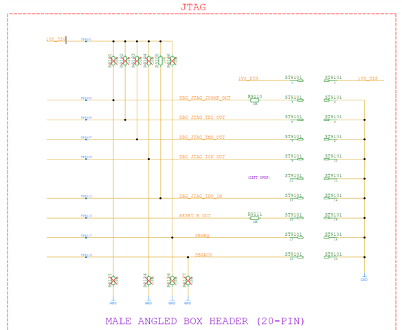
On a custom board, the following conditions cause SC_ERR_PATH_BROKEN:
|
Condition
|
Effect
|
|---|---|
|
TDO pin floating or pulled incorrectly
|
Stuck-at-zero or stuck-at-one
|
|
TDI/TMS/TCK not reaching the device
|
No scan chain response
|
|
Reset (nTRST or nSRST) held asserted
|
Device not exiting reset, JTAG inactive
|
|
Missing pull-up/pull-down on JTAG pins
|
Signal levels not meeting threshold
|
Action:
The AWR2x44P has configurable boot modes and security states that can disable or restrict JTAG access:
Action:
This is an important diagnostic point. The XDS110 passing "Test Connection" does not necessarily confirm the JTAG chain is fully functional. The XDS110 "Test Connection" in some configurations performs a less strict check. It is possible that:
Action:
Step 1 — Measure VTREF voltage: Using a multimeter, measure Pin 1 of the ARM20 connector on your custom board with the board powered. Confirm the voltage matches the AWR2x44P JTAG I/O supply.
Step 2 — Check nRESET/nTRST state: Confirm these signals are not being held asserted on your custom board. Measure Pin 15 (nTRST) and Pin 10 (nRESET) of the ARM20 connector.
Step 3 — Verify XDS110 actually connects to a core: In CCS with XDS110, attempt a full debug session, not just Test Connection. Report whether it successfully halts the R5F or DSP core.
Step 4 — Review AWR2x44P boot mode pins: Consult the AWR2x44P datasheet and confirm the SOP (Safe Operating Procedure) pin configuration on your custom board is set for functional/debug mode.
|
Finding
|
Conclusion
|
|---|---|
|
Error -233 SC_ERR_PATH_BROKEN
|
Target JTAG scan chain not responding
|
|
Firmware v1.0.0.9 confirmed
|
XDS200 probe is functioning correctly
|
|
Low JTAG frequency did not help
|
Not a signal integrity/speed issue
|
|
XDS110 passes Test Connection
|
Needs verification of full debug capability
|
|
Custom board
|
JTAG pin configuration must be verified
|
The most productive next step is to verify VTREF voltage and JTAG pin states on your custom board, and to confirm whether the XDS110 can perform an actual debug session beyond the Test Connection check.
Please share your findings from the VTREF measurement and the XDS110 full connection attempt.
Best Regards,
Zackary Fleenor
Hello,
1. and 2. VTREF Measurement and Signal Comparison
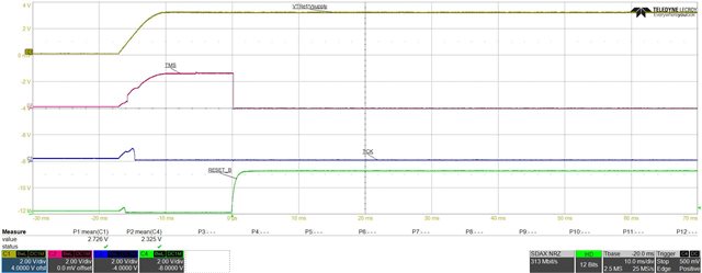
I measured VTREF, TMS, nRESET, and TCK on the custom board using both debuggers:
XDS110:

XDS200:


Additional Observation
During testing, I noticed a consistent difference in behavior between the two debuggers when performing a hard reset of the power supply:
With the XDS110 connected:
With the XDS200 connected:
This difference appears consistently and may indicate a variation in how the two debuggers drive or hold the JTAG lines during reset.
3.
Regarding the SOP (boot mode) pins:
4. XDS110 Debug Capability (Full Connection Test)
With the XDS110, I can successfully go beyond "Test Connection":
This confirms that:
At this point, the discrepancy appears to be specific to the XDS200 interaction with this setup, despite identical hardware conditions.
Please let me know if there are any additional checks you would like me to perform.
Best regards,
Mihaela
| Condition | VTREF / Supply | TMS |
|---|---|---|
| XDS110 connected | ~1.5V (normal) | ~3V+ (normal) |
| XDS200 connected | ~0.6 mV (collapsed) | 0V (pulled low) |
| Factor | XDS110 | XDS200 |
|---|---|---|
| VTREF current draw | Low (~1–2 mA) | Higher (~10–20 mA for I/O buffers) |
| VTREF dependency | Less critical | Required to power internal level translators |
| Tolerance to weak VTREF | Higher | Lower — collapses under load |
| Finding | Conclusion |
|---|---|
| VTREF collapses to ~0.6 mV with XDS200 | VTREF source on custom board is too high impedance |
| TMS drops to 0V | Direct consequence of collapsed VTREF (level translators unpowered) |
| XDS110 doesn't cause collapse | XDS110 draws negligible current from VTREF |
| Error -233 SC_ERR_PATH_BROKEN | Expected result when VTREF = 0V (no JTAG signals possible) |
| Firmware, frequency, boot mode all ruled out | Confirmed hardware supply design issue |