AM67: AM67 IBIS Model and LVCMOS_V MAIN Domain I2C0_XX

Part Number: AM67

Hello TI team,

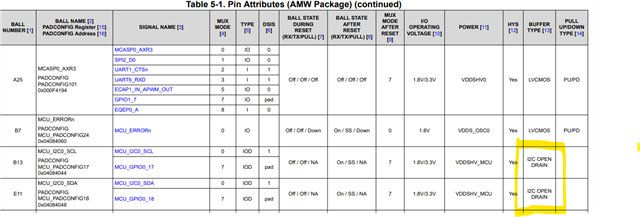
I have a question regarding the J722S IBIS model that is publically provided. From what I understand the IBIS model used for the Main Domain I2C0_XX called LVCMOS_V. I want to confirm if this is the correct model is to use and not the IIC_V model that is used which I believe is dedicated the MCU domain MCU_I2C0_XX and acts as a true I2C open drain model..
From what I understand the I2C0 is an Push Pull LVCMOS bus that is emulated to act as an open-drain when driven high. From what I deciphered LVCMOS_V are the models used for LVCMOS Emulated Open Drain buffers (IOD - LVCMOS), and the LVCMOS_H are the models that act as standard LVCMOS Push Pull IO. For LVCMOS_V I assume I can drive the buffers they can be converted from push-pull to OD, also if I were to use the LVCMOS_V I assume I would have to shut off the internal source, or the model will drive the symbol correct?

  • Hello Nicolas Rancher,

    Thank you for the query.

    I have a question regarding the J722S IBIS model that is publically provided. From what I understand the IBIS model used for the Main Domain I2C0_XX called LVCMOS_V. I want to confirm if this is the correct model is to use and not the IIC_V model that is used which I believe is dedicated the MCU domain MCU_I2C0_XX and acts as a true I2C open drain model..

    This is correct.

    Open drain I2C buffer

    Emulated Open drain I2C buffer

    Regards,

    Sreenivasa

  • Hello Nicolas Rancher,

    From what I understand the I2C0 is an Push Pull LVCMOS bus that is emulated to act as an open-drain when driven high. From what I deciphered LVCMOS_V are the models used for LVCMOS Emulated Open Drain buffers (IOD - LVCMOS), and the LVCMOS_H are the models that act as standard LVCMOS Push Pull IO. For LVCMOS_V I assume I can drive the buffers they can be converted from push-pull to OD, also if I were to use the LVCMOS_V I assume I would have to shut off the internal source, or the model will drive the symbol correct?
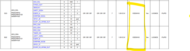
    Let me check with the team and update you on this query.

    Regards,

    Sreenivasa

  • Hello Nicolas Rancher,

    Please refer inputs i received from the experts:

    From what I understand the I2C0 is an Push Pull LVCMOS bus that is emulated to act as an open-drain when driven high. From what I deciphered LVCMOS_V are the models used for LVCMOS Emulated Open Drain buffers (IOD - LVCMOS), and the LVCMOS_H are the models that act as standard LVCMOS Push Pull IO. For LVCMOS_V I assume I can drive the buffers they can be converted from push-pull to OD, also if I were to use the LVCMOS_V I assume I would have to shut off the internal source, or the model will drive the symbol correct?

    LVCMOS_H and LVCMOS_V refer to the orientation of the IO within the IO ring – H for horizontal and V for vertical. Both have the same functionality that can be controlled by appropriate buffer tie-offs in the simulation setup.

    To emulate the open-drain function, we simply tie the input of the output buffer low and connect the I2C output signal to the output enable of the output buffer.  In this usage of the IO, the high driver is never turned on.  When the output is driven low, the low driver will perform the same way it does in push-pull mode.  I would expect customers to use the same IBIS model and simply connect the buffer in their simulations as described above.

    Regards,

    Sreenivasa

  • Could you clarify more about what you mean regarding "To emulate the open-drain function, we simply tie the input of the output buffer low and connect the I2C output signal to the output enable of the output buffer."
    Is this happening inherently in the buffer, or do I need to do some more configuration?

    Another question, for the LVCMOS_H and LVCMOS_V slow, nominal, fast models. Those models are not included in LVCMOS_H and LVCMOS_V libraries. Do you know why or did the IBIS model developer for the AM67 forget the to include the models in the library. I see the models within the J722S.ibs, they are just not attached to library.

  • Hello Nicolas Rancher,

    Thank you.

    Could you clarify more about what you mean regarding "To emulate the open-drain function, we simply tie the input of the output buffer low and connect the I2C output signal to the output enable of the output buffer."
    Is this happening inherently in the buffer, or do I need to do some more configuration?

    In case you are looking to simulate I2C interface with the LVCMOS buffer type, i would expect that this is expected to be done by the user.

    Can you confirm if you are looking to perform some simulations related to Emulated Open-drain and i can check internally.

    REgards,

    Sreenivasa

  • Hello Nicolas Rancher,

    Another question, for the LVCMOS_H and LVCMOS_V slow, nominal, fast models. Those models are not included in LVCMOS_H and LVCMOS_V libraries. Do you know why or did the IBIS model developer for the AM67 forget the to include the models in the library. I see the models within the J722S.ibs, they are just not attached to library.

    Drive strength configuration is not supported. The only drive strength supported in the nominal.

    Is there a use case for you to set FAST. 

    Regards,

    Sreenivasa

  • Looking at these models they seem like duplicates.
    Are these models not valid?

    The drive strength is a characteristic for the bus and the simulation. It would be great to have the different drive
    strengths for pre-sims.

    |***************************************************************************
    | fast_3p3_v
    |***************************************************************************
    [Model] lvcmos0_fast_3p3_v
    Model_type I/O
    Polarity Non-Inverting
    Enable Active-High
    Vinl = 0
    Vinh = 0.8
    Vmeas = 1.65
    Vref = 3.3
    Cref = 2pF
    Rref = 100000
    |
    | typ min max
    |
    C_comp 3.777pF 3.679pF 3.786pF
    [Voltage Range] 3.3 2.97 3.63
    [Temperature Range] 27 150 -40
    [Pullup Reference] 3.3 2.97 3.63
    [Pulldown Reference] 0 0 0
    [Power Clamp Reference] 3.3 2.97 3.63
    [GND Clamp Reference] 0 0 0
    |
    |***************************************************************************

    |************************************************************************
    | slow_3p3_v
    |************************************************************************
    [Model] lvcmos0_slow_3p3_v
    Model_type I/O
    Polarity Non-Inverting
    Enable Active-High
    Vinl = 0
    Vinh = 0.8
    Vmeas = 1.65
    Vref = 3.3
    Cref = 2pF
    Rref = 100000
    |
    | typ min max
    |
    C_comp 3.777pF 3.679pF 3.786pF
    [Voltage Range] 3.3 2.97 3.63
    [Temperature Range] 27 150 -40
    [Pullup Reference] 3.3 2.97 3.63
    [Pulldown Reference] 0 0 0
    [Power Clamp Reference] 3.3 2.97 3.63
    [GND Clamp Reference] 0 0 0
    |
    |***************************************************************************

  • I am looking to simulate the I2C busses. I am not understanding how your team simulated the emulated open-drain buffer. Do I need to place an external buffer and connect the I2C out to the enable pin, or does this happen internally and no configuration externally is needed on my side?

  • Hello Nicolas Rancher,

    Thank you.

    Let me check internally with the simulation expert.

    Regards,

    Sreenivasa 

  • Hello Nicolas,

    In order to simulate I2C, you have to modulate the output enable to ensure that the driver only pulls the signal low (open drain). To pull the signal high, disable the driver and allow the pullup resistor to pull the line high. Here are examples of a correct and incorrect setup (simple load capacitor used as load).

    Correct:

    Incorrect:

    With regards to your question about the models being duplicates, while the headers are the same because the different drive strengths share many properties, the I-V and V(t) tables for these two models are different. Most of the data of an IBIS model is contained in these tables.

    Regards,

    Seif

  • So, these are different models that have drive strengths based on the name? lvcmos0_fast_3p3_v, lvcmos0_slow_3p3_v

  • Yes, that's correct

  • Okay thank you. Do you know why the models were not included in the model selectors for LVCMOS_H and LVCMOS_V? (I previously referred to model selector as "library".)

  • Hey Nicolas, this is likely because certain pins such as D23 do not support adjustable drive strength. I2C is fairly low speed so changing the drive strength is usually not necessary.