Part Number: TINA-TI
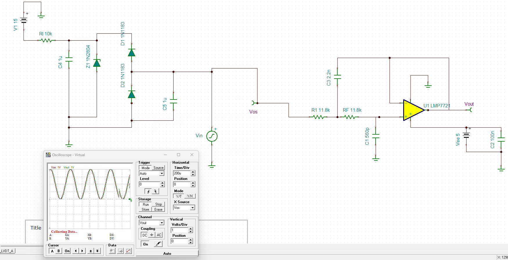
I created a simulation of a circuit that failed. I thought the failure might be an open resistor. I opened the resistor in the simulation and thought it resembled the issue. I then took a good board and removed the resistor and got a different result. So my schematics and real life do not match.
I attempted to attach the simulation. I am not sure what files you need. In the simulation I removed R1 and the output went to 2.5V. On the actual board if I remove the resistor the output of the opamp went to 0.25V.
In addition on the board with the real problem I believe the voltage goes to about 3.05V. I believe it involves an open circuit as the output seems to pick up nice and follows the output of the other op-amp in the package. Also in trying to debug the circuit, I probed R1 and the problem went away. So I was suspecting a cold solder joint at R1 and was trying to prove it with using TINA.
I am trying to be careful about disrupting the bad board and so I am trying to force a good board to have the same issue but as the simulation and good board do not match when I remove R1 I am trying to figure out what is wrong with my simulation.
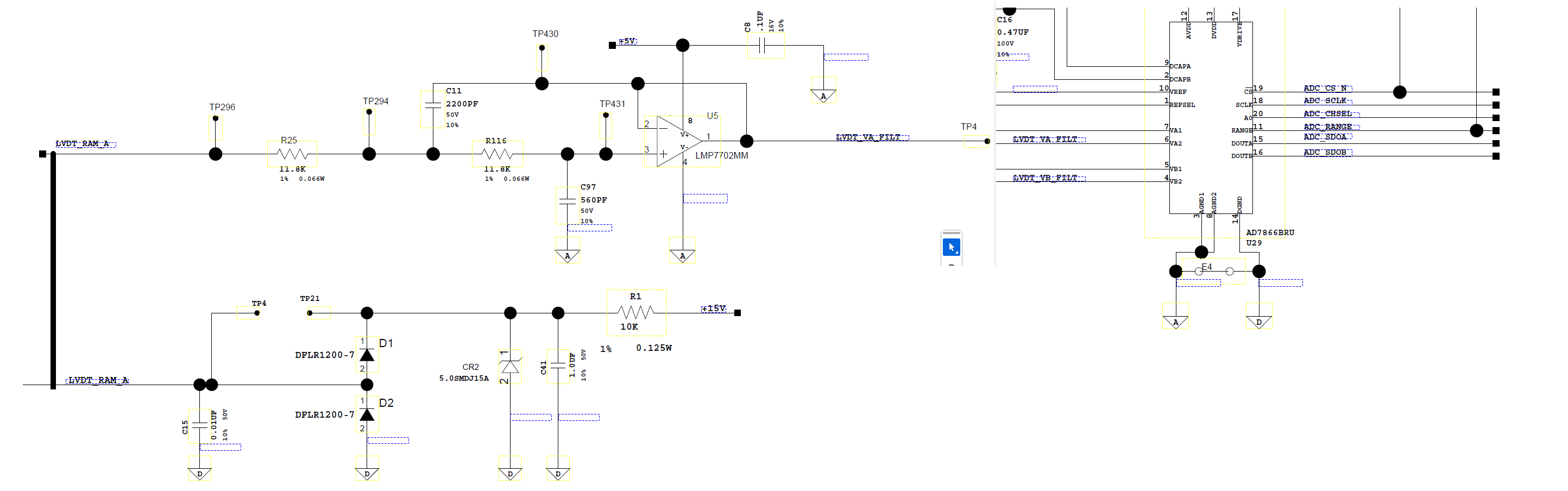
Also attached are pictures of the simulated circuit and the real circuit. Let me know if you see I did not simulate the circuit correctly.