PSPICE-FOR-TI: UV and OV simulations using the TPS2663

Part Number: PSPICE-FOR-TI

Hi everyone, I’m trying to simulate the circuit I’ve designed using the TPS26631. I have attached the project for you to run a simulation on.

Vi = [44 .. 50]V

Ii = [0 .. 5]A

Vuv= 40V

Vov = 60V
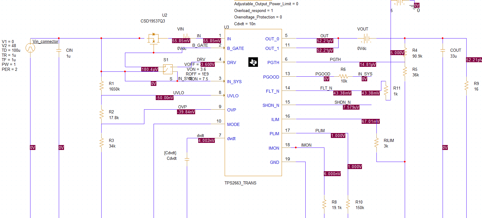
image.png

image.png


1) Here I set Vi=62V > OV threshold 60V --> overvoltage, everything should be fine, shouldn’t it? The Vout is deactivated
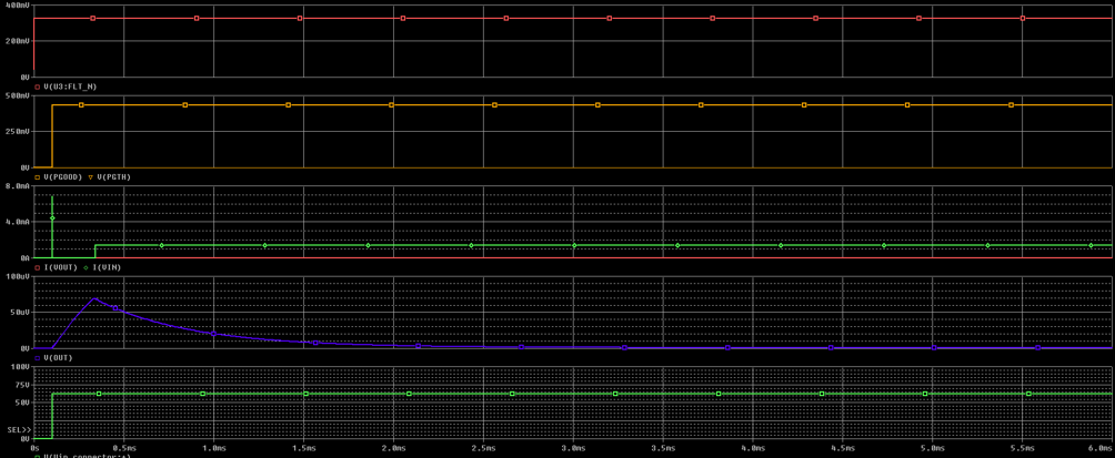
image.png

2) Here I set Vi=38V < UV threshold 40V --> undervoltage .. but I don’t understand why, when I set Vi to 38V for the undervoltage fault (which is below the 40V threshold), I don’t get the same behaviour as I do with overvoltage
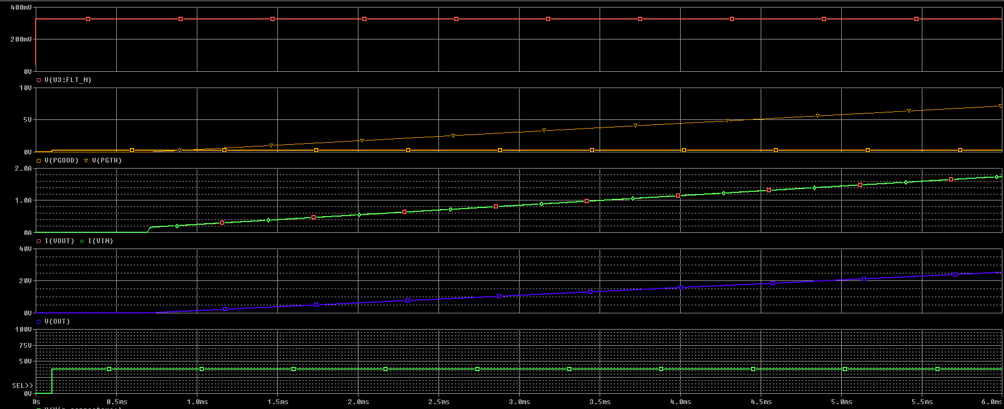
image.png

3) Generally speaking, how should I connect FLTN? In your default TPS2663x circuit (downloaded from here), you had connected it with 24k res to VIN_SYS, but as I’ll be feeding it to a GPIO pin on my microcontroller, does it make sense to connect it to a 5V power supply with a 1k pull-up resistor?

4) More on the FLTN pin, I don’t know whether it’s because I connected it incorrectly or not, but its behaviour during overvoltage and undervoltage doesn’t seem right to me… it should be brought down to 0V in the event of a fault, which isn’t happening

 5) How do I simulate on PSpice for Ti reverse polarity and reverse current?

TPS2663 simulazione NUOVA 2.rar 

  • Hi,

    I will get back to you by the end of today.

    thanks,

    Hemanth

  • seems like Fault pin is not model correctly for UVLO & OVLO.

    Fault pin can be connected to external pull up.

    they did not model the reverse polarity, reverse current you can check by increasing the output voltage bit higher than VIN during normal operating condition, then verify whether device is turning off or not.

    thanks,

    Hemanth

  • reverse current you can check by increasing the output voltage bit higher than VIN during normal operating condition, then verify whether device is turning off or not

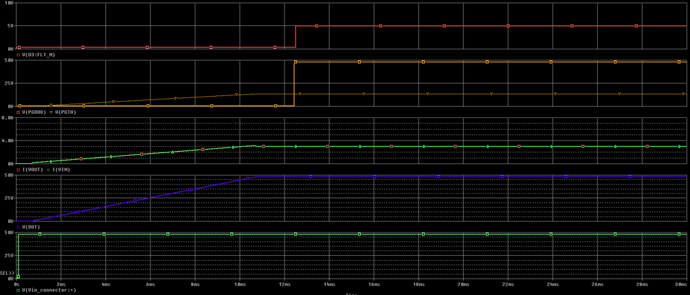
    There are 48V at the input (green trace), then I’ve connected a voltage generator to the output which rises to 60V (pink trace) after about 5ms – so with a slight delay. It doesn’t seem to me that the device switches off; indeed, it actually switches on when Vou is applied !!

    I keep wondering whether I’m doing something wrong or whether your model isn’t complete/correct .. as far as I’m aware, the fault pin isn’t modelled correctly at the moment, nor is reverse polarity, nor is OVP, nor is reverse current… but, as I said, I might be wrong. I look forward to your feedback

  • when VOUT is in steady state i mean VIN = VOUT (device is on) , then increase VOUT slightly higher than VIN around 2V to 3V

    thanks,

    Hemanth