This thread has been locked.

If you have a related question, please click the "Ask a related question" button in the top right corner. The newly created question will be automatically linked to this question.

TUSB8041-Q1: USB HUB (ethernet)

Part Number: TUSB8041-Q1
Other Parts Discussed in Thread: TUSB8041EVM, TUSB8041, HD3SS3212-Q1, TPS2001C

My name is Juan Jacinto Montenegro, and I am an Electronics Engineer at Rother.

We are currently developing a portable ADA system intended to operate inside a vehicle. Our main processing module provides a USB 2.0/USB 3.1 interface and operates as the USB Host.

During our evaluation and validation activities, we have successfully connected an external USB hub to the USB Type-C port of the module. Multiple USB peripherals can then be connected through the hub, including a keyboard, a mouse, and a USB-to-Ethernet adapter.

For our custom PCB, we would like to integrate a similar USB hub architecture directly onto the board instead of using an external USB hub. The hub would be connected to the USB Host interface of the main processing module through its upstream port, while its downstream ports would provide the following interfaces:

  • One external USB Type-C port.
  • One external USB Type-A port.
  • One Ethernet interface implemented through a USB-to-Ethernet controller.
  • One internal USB connection for communication with our onboard MCU, which would operate as a USB device.

The proposed architecture is:
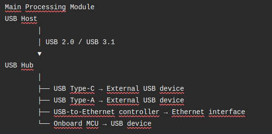
imagen.png

The USB hub would be connected to the main processing module through its upstream port. The downstream ports would be used to connect the external USB interfaces, the USB-to-Ethernet controller, and our onboard MCU.

Since the final product is intended to operate inside a vehicle, we would preferably like to use automotive-qualified components. We are therefore evaluating solutions such as the TUSB8041-Q1 and would appreciate your recommendations regarding the most suitable TI USB hub for this application.

Could you please let us know whether TI provides any of the following resources that could be useful for our design?

  • Automotive-qualified USB 3.x hub reference designs.
  • Evaluation modules with complete schematics, PCB layout files, BOMs, and design documentation.
  • Reference designs combining USB Type-C and USB Type-A downstream ports.
  • Design guidance for connecting an onboard MCU through an internal USB interface.
  • Recommendations regarding USB 3.x signal integrity, routing, ESD protection, VBUS power distribution, and port power management.

Regarding the Ethernet interface, we understand that TI may not provide a dedicated USB-to-Ethernet controller for this application. Therefore, we are considering using a USB-to-Ethernet controller from another manufacturer, such as the Realtek RTL8153 or the Microchip LAN7800, connected to one of the downstream ports of the TI USB hub.

We have found discussions on the TI E2E forum where similar architectures have been considered. Could you please confirm whether this implementation is supported and whether TI has any relevant reference designs, application notes, or design recommendations?

We would particularly appreciate any available reference design or evaluation board that could help us analyze the complete implementation and adapt it to our custom automotive PCB.

Thank you in advance for your support and recommendations.

Best regards,

  • Hi Juan,

    Could you please let us know whether TI provides any of the following resources that could be useful for our design?

    • Automotive-qualified USB 3.x hub reference designs.
    • Evaluation modules with complete schematics, PCB layout files, BOMs, and design documentation.
    • Reference designs combining USB Type-C and USB Type-A downstream ports.
    • Design guidance for connecting an onboard MCU through an internal USB interface.
    • Recommendations regarding USB 3.x signal integrity, routing, ESD protection, VBUS power distribution, and port power management.

    We have a few different app notes, reference designs, and EVMs that you can use for design your system, yes! I'll post links to them below:

    I sent you a friend request on E2E, if you accept that I can send you the EVM design files.

    You are correct that we do not have any USB to Ethernet bridges, so you will need to use one from a different manufacturer.

    How exactly do you plan to interface the MCU with the hub?

    Thanks,

    Ryan

  • Hi Ryan Kitto,

    Thank you for your response and for sharing the documentation and application resources.

    • Regarding the E2E friend request, I have checked my account, but I cannot see the request. Could you please verify whether it was sent correctly or send it again?
    • We would be very interested in receiving the schematic and design files for the TUSB8041EVM, as the TUSB8041-Q1 is particularly relevant to our application due to its AEC-Q100 qualification and its suitability for an automotive environment.
    • Regarding the onboard MCU connection, our intention is to connect the MCU internally to one of the downstream ports of the USB hub. Unlike the external USB Type-C, USB Type-A and Ethernet ports, this USB connection would not be routed to an external physical connector.

    Instead, the USB differential pairs between the hub and the MCU would be permanently routed on our custom PCB. Therefore, the MCU would remain directly connected to the USB hub at all times and, through the hub, to the main processing module, which operates as the USB Host.

    The intended architecture would be:

    Main Processing Module
    USB Host
            │
            │ USB 3.1
            ▼
    TUSB8041-Q1
    USB Hub
            │
            ├── External USB Type-C port
            ├── External USB Type-A port
            ├── USB-to-Ethernet controller → RJ45
            └── Internal USB connection → Onboard MCU
                                          (permanently connected)

    The onboard MCU would operate as a USB device, while the main processing module would remain the USB Host. The USB hub would provide the internal connection between both devices.

    Please let us know if you have any specific recommendations regarding the implementation of this permanently connected internal USB interface, including routing, termination, power management, reset behavior, or hub port configuration.

    Thank you again for your support. We look forward to receiving the TUSB8041EVM design files.

  • Hi Juan,

    Regarding the E2E friend request, I have checked my account, but I cannot see the request. Could you please verify whether it was sent correctly or send it again?

    I re-sent the friend request. However, you can also check and/or send it on your side by clicking on my name on E2E and pressing the "+Connect" button to the right of my name:

    We would be very interested in receiving the schematic and design files for the TUSB8041EVM, as the TUSB8041-Q1 is particularly relevant to our application due to its AEC-Q100 qualification and its suitability for an automotive environment.

    Once we are friends on E2E, I can send these files over.

    Regarding the onboard MCU connection, our intention is to connect the MCU internally to one of the downstream ports of the USB hub. Unlike the external USB Type-C, USB Type-A and Ethernet ports, this USB connection would not be routed to an external physical connector.

    This should be okay. Is the MCU going to be a SS connection or a HS connection, just curious.

    One question I have want confirm, is the MCU being powered externally without the need for a USB connection, correct?

    Please let us know if you have any specific recommendations regarding the implementation of this permanently connected internal USB interface, including routing, termination, power management, reset behavior, or hub port configuration.

    Section 9.2.1.2 provides details and examples on how to configure the USB ports, VBUS power switches, as well as controlling RSTN and the crystal:

    For timing, please ensure the power-up timing listed in section 7.6 of the datasheet is being followed:

    Thanks,

    Ryan

  • Hi Ryan Kitto,

    1. Regarding the USB connection between the hub and the onboard MCU, the MCU will use a USB 2.0 Full-Speed (FS) interface, with a maximum data rate of 12 Mbps. We understand that this should not present any issue, since the TUSB8041-Q1 supports USB Full-Speed, High-Speed, and SuperSpeed devices on its downstream ports.
    2. Regarding the MCU power supply, your understanding is correct. The MCU will be powered externally by its dedicated power-supply circuitry and will not be powered through the USB connection. Therefore, the USB connection between the TUSB8041-Q1 and the MCU will be used exclusively for data communication. The MCU will remain powered independently of the USB VBUS supplied by the hub.
    3. On the other hand, I’m trying to accept the request, but it’s having no effect:

    Regards

  • Hi Ryan Kitto,

    While reviewing the USB interface of the CQS290 module and evaluating the integration of the TUSB8041-Q1 into our custom PCB, we identified a question regarding the connection between the CQS290 and the upstream port of the hub.

    The CQS290 exposes the following USB-related signals externally:

    • USB_VBUS_IN
    • USB0_DP
    • USB0_DM
    • USB0_CC1
    • USB0_CC2
    • USB0_SS_RX0_P
    • USB0_SS_RX0_N
    • USB0_SS_TX0_P
    • USB0_SS_TX0_N
    • USB0_SS_RX1_P
    • USB0_SS_RX1_N
    • USB0_SS_TX1_P
    • USB0_SS_TX1_N

    The CQS290 USB interface is currently validated using the evaluation board, where an external USB hub is connected through the USB Type-C connector. In this configuration, the CQS290 operates as the USB Host, while the external hub operates as a USB device connected to the CQS290.

    For our custom PCB, we would like to integrate the TUSB8041-Q1 directly onto the board and connect the CQS290 USB interface directly to the upstream port of the hub, without using an intermediate USB Type-C receptacle or cable.

    However, the CQS290 does not expose a single conventional set of upstream SuperSpeed signals such as:

    • SSTX_P/N
    • SSRX_P/N
    • USB_DP
    • USB_DM

    Instead, it exposes two sets of SuperSpeed pairs, corresponding to the two possible USB Type-C orientations:

    • USB0_SS_TX0_P/N
    • USB0_SS_RX0_P/N
    • USB0_SS_TX1_P/N
    • USB0_SS_RX1_P/N

    It also exposes USB0_CC1, USB0_CC2, and USB_VBUS_IN.

    Could you please advise on the recommended architecture for connecting this Type-C-oriented USB interface directly to the upstream port of the TUSB8041-Q1?

    In particular, we would appreciate your guidance regarding the following points:

    1. Can one set of the CQS290 SuperSpeed pairs, for example TX0/RX0, be connected directly to the TUSB8041-Q1 upstream SuperSpeed interface, while leaving the second set unconnected?
    2. Alternatively, would an external SuperSpeed orientation MUX be required to connect the CQS290 to the hub upstream port?
    3. If an external MUX is required, could you recommend a suitable TI device or reference architecture?
    4. Since there will be no physical USB Type-C receptacle between the CQS290 and the onboard hub, how should USB0_CC1 and USB0_CC2 be configured on the CQS290 side?
    5. Would the hub side require external Rd pull-down resistors or a USB Type-C controller to allow the CQS290 to detect the onboard hub correctly?
    6. How should USB_VBUS_IN be connected in this configuration? Should it be connected to the hub upstream VBUS supply, and are any additional power-control or sequencing circuits required?
    7. Does TI have any reference design showing a USB Type-C Host connected directly to the upstream port of a TUSB8041-Q1 without an intermediate USB Type-C connector?

    Our intended architecture is:

    CQS290
    USB Type-C Host interface
            │
            │ USB 2.0 + USB 3.x SuperSpeed
            │
            ▼
    TUSB8041-Q1
    Integrated USB 3.x Hub
            │
            ├── External USB Type-C port
            ├── External USB Type-A port
            ├── USB-to-Ethernet controller
            └── Internal USB connection to the onboard MCU

    We understand that some of the CQS290-specific implementation details may need to be confirmed directly with Cavli. However, we would greatly appreciate TI’s guidance regarding the TUSB8041-Q1 side and the recommended way to interface a Type-C-oriented USB Host implementation with the hub’s upstream port.

    Thank you in advance for your support.

    Best regards,

  • Hi Juan,

    • Regarding the USB connection between the hub and the onboard MCU, the MCU will use a USB 2.0 Full-Speed (FS) interface, with a maximum data rate of 12 Mbps. We understand that this should not present any issue, since the TUSB8041-Q1 supports USB Full-Speed, High-Speed, and SuperSpeed devices on its downstream ports.
    • Regarding the MCU power supply, your understanding is correct. The MCU will be powered externally by its dedicated power-supply circuitry and will not be powered through the USB connection. Therefore, the USB connection between the TUSB8041-Q1 and the MCU will be used exclusively for data communication. The MCU will remain powered independently of the USB VBUS supplied by the hub.

    Correct, these should all be okay.

    Can one set of the CQS290 SuperSpeed pairs, for example TX0/RX0, be connected directly to the TUSB8041-Q1 upstream SuperSpeed interface, while leaving the second set unconnected?

    That should work, yes. The CQS290 may need to be set to only enable the signal to come through one of those differential pairs.

    Alternatively, would an external SuperSpeed orientation MUX be required to connect the CQS290 to the hub upstream port?

    A SS Mux should only be needed if the upstream connection is actively going to be switched. If the connection between the CQS290 and the TUSB8041 will not change from TX0/RX0, then no mux should be needed.

    If an external MUX is required, could you recommend a suitable TI device or reference architecture?

    If for some reason one is required, I would recommend the HD3SS3212-Q1.

    Since there will be no physical USB Type-C receptacle between the CQS290 and the onboard hub, how should USB0_CC1 and USB0_CC2 be configured on the CQS290 side?

    I would check with the CQS290 team to confirm and get their guidance., but I believe you can configure the CC pins of the CQS290 such that the CQS290 configures as a DFP device by pulling one of the CC pins down.

    Would the hub side require external Rd pull-down resistors or a USB Type-C controller to allow the CQS290 to detect the onboard hub correctly?

    If this is all being done on one board without a separate type-C connection, only RD pull-downs should be needed to control the CQS290 CC pins. CC controllers should only be needed if there is a physical type-C connection.

    How should USB_VBUS_IN be connected in this configuration? Should it be connected to the hub upstream VBUS supply, and are any additional power-control or sequencing circuits required?

    I would recommend connecting USB_VBUS to the upstream VBUS supply, yes. Please ensure the 5V rail is being properly divided down to ensure 5V does not reach the pin:

    Does TI have any reference design showing a USB Type-C Host connected directly to the upstream port of a TUSB8041-Q1 without an intermediate USB Type-C connector?

    Unfortunately I don't believe we have any design that showcases a type-C host connecting to the US port of our hub with no external connection. However, as long as the data lanes are correctly routed and the host is configured correctly, I see no reason why it shouldn't work.

    I would definitely recommend reaching out to Cavli and double checking aspects like the CC pins with them.

    Thanks,

    Ryan

  • Hi Ryan Kitto,

    All right, I’ll check this information with the manufacturer.

    I have one additional question regarding the downstream ports of the TUSB8041-Q1.

    One of the downstream ports will be permanently connected to our onboard MCU. The MCU only supports USB 2.0 Full-Speed (12 Mbps) and therefore only requires the D+ and D− differential pair.

    In this case, the SuperSpeed interface of that downstream port will never be used.

    Could you please confirm the recommended implementation for this scenario?

    Specifically:

    1. Can the SuperSpeed TX/RX differential pairs of that downstream port simply be left unconnected (No Connect), while only routing the USB 2.0 D+ and D− signals to the MCU?
    2. Are any termination components or specific routing recommendations required for the unused SuperSpeed pairs?
    3. Is there any recommended schematic or application note showing the connection of a USB 2.0 Full-Speed-only device to one of the TUSB8041-Q1 downstream ports?

    Our intention is for this downstream port to be dedicated exclusively to the onboard MCU, which will always operate as a USB 2.0 Full-Speed device.

    Thank you again for your support.

    Best regards,

    Juan

  • Hi Juan,

    • Can the SuperSpeed TX/RX differential pairs of that downstream port simply be left unconnected (No Connect), while only routing the USB 2.0 D+ and D− signals to the MCU?
    • Are any termination components or specific routing recommendations required for the unused SuperSpeed pairs?

    If the SS lanes of the downstream port are not being used, they can be left floating. No specific terminations or routing is needed.

    Is there any recommended schematic or application note showing the connection of a USB 2.0 Full-Speed-only device to one of the TUSB8041-Q1 downstream ports?

    I don't believe we have any app note or schematic for specifically a USB2 only implementation on a USB3 hub. However leaving the SS pins floating with only the USB2 lanes connected should be all it takes to have the port configured for only USB2 support.

    Thanks,

    Ryan

  • Hi Ryan Kitto,

    Thank you for the clarification.

    We have one additional question regarding the PCB layout of this downstream port.

    Since this particular downstream port of the TUSB8041-Q1 will be permanently used only for our MCU, which operates as a USB 2.0 Full-Speed device (12 Mbps), and the SuperSpeed TX/RX pairs will be left unconnected as you recommended:

    Should we follow the USB 3.x / SuperSpeed PCB layout and routing recommendations for this entire downstream port because the TUSB8041-Q1 is a USB 3.x hub, or can we follow the USB 2.0 PCB layout recommendations for the D+ and D− differential pair?

    In particular, we would like to confirm whether the following can be designed according to USB 2.0 Full-Speed requirements:

    • D+ / D− differential impedance and routing.
    • Trace length and length matching.
    • Spacing and routing constraints.
    • Number of vias and layer transitions.
    • General PCB layout requirements for the USB 2.0 differential pair.

    Our understanding is that, since the SuperSpeed lanes are not used and only D+ and D− are connected to the MCU, the routing requirements for this connection should be based on USB 2.0 Full-Speed, rather than USB 3.x SuperSpeed.

    Could you please confirm if this understanding is correct?

    Best regards,

    Juan

  • Hi Juan,

    Should we follow the USB 3.x / SuperSpeed PCB layout and routing recommendations for this entire downstream port because the TUSB8041-Q1 is a USB 3.x hub, or can we follow the USB 2.0 PCB layout recommendations for the D+ and D− differential pair?

    If the SS pins are not going to be used on this port, you can follow the USB2 layout recommendations for D+/D-. You can also follow these same recommendations for D+/D- on the other 3 downstream ports. 

    We do have some recommendations for the SS and HS layout, you can find those here in this app note:

    High-Speed Layout Guidelines for Signal Conditioners and USB Hubs (Rev. A)

    Trace length and length matching.

    For a FS connection, trace length is not as much of a concern since it has a much lower frequency than SS signaling. I would recommend keeping the trace between the downstream port and within 12 inches if possible. The intra-pair skew should be kept as low as possible.

    Number of vias and layer transitions.

    Preferably, keep the number of vias as low as possible.

    Our understanding is that, since the SuperSpeed lanes are not used and only D+ and D− are connected to the MCU, the routing requirements for this connection should be based on USB 2.0 Full-Speed, rather than USB 3.x SuperSpeed.

    Yes, correct. For D+/D-, you should follow USB2 guidelines rather than USB3 guidelines.

    Thanks,

    Ryan

  • Hi Ryan Kitto,

    I have some questions regarding the signals on the TUSB8041-Q1:

    1. FULLPWRMGMTz/SMBA1/SSUP
      The description table in the datasheet states that it has an internal pull-down; therefore, if you want 0 = Power switching and over-current inputs supported, I understand that this pin could be left unconnected.

      However, the same datasheet contains the following diagram showing it connected to an external pull-down:

      What would be the correct connection for that pin?
    2. The same applies to the GANGED/SMBA2/HS_UP, TEST signals
    3. I have a question regarding the battery charging functionality and the AUTOENz pin of the TUSB8041-Q1.

      As I understand it, the AUTOENz signal enables automatic mode for downstream ports that have battery charging mode enabled.

      In this regard, I have some doubts about the intended configuration.

      My understanding is that the Battery Charging mode is intended to allow a device connected to a downstream port of the hub to be charged, in addition to providing the USB connection.

      According to the datasheet, Battery Charging mode for each downstream port is enabled by connecting a pull-up resistor to the corresponding PWRCTLx_BATENx pin.


      For our application, however, the purpose of the downstream ports is
      USB data communication only. We do not intend to use the TUSB8041-Q1 to charge any device connected to its downstream ports.

      Therefore, could you please confirm whether the following configuration is correct?

      • We should not connect the pull-up resistors on PWRCTLx_BATENx associated with Battery Charging mode.
      • Since Battery Charging mode would not be enabled on any downstream port, the AUTOENz function would not be required.
      • AUTOENz can therefore be left unconnected, relying on its internal pull-up, which corresponds to 1 = Automatic Mode is disabled.

      Could you please confirm that this is the correct configuration for a design where the downstream ports are intended exclusively for USB data communication and no battery charging functionality is required?

    Best regards,

    Juan

  • Hi Juan,

    What would be the correct connection for that pin?

    This pin can be left floating, a PD resistor is not required.

    The same applies to the GANGED/SMBA2/HS_UP, TEST signals

    You can also leave this pin floating.

    • We should not connect the pull-up resistors on PWRCTLx_BATENx associated with Battery Charging mode.
    • Since Battery Charging mode would not be enabled on any downstream port, the AUTOENz function would not be required.
    • AUTOENz can therefore be left unconnected, relying on its internal pull-up, which corresponds to 1 = Automatic Mode is disabled.

    Yes, your understanding is correct. Both these pins can be left floating if their respective functionality is not being used.

    Thanks,

    Ryan

  • Hi Ryan Kitto,

    Thank you for the information you have provided.

    I am implementing Type C as a downstream (DFP) connection for one of the HUB’s downstream ports. According to the HD3SS3220IRNHR datasheet, the following pull-up value is recommended for the PORT pin:

    Furthermore, based on the calculations made for Vih = VDD5 – 0.3; Iih = 20 µA; VDD5 = 5 V, I get that R must be less than 15 kΩ.

    However, in the same datasheet, in the example for DFP mode, they show the following circuit with a 200 kΩ pull-up resistor:

    What would be the correct value?

    Best regards,

    Juan

  • Hi Juan,

    What would be the correct value?

    I would recommend the 4.7Kohm resistor value for the PORT pin. While the 200Kohm value does likely work, we use 4.7Kohm typically, and it is the value used in our EVMs.

    Thanks,

    Ryan

  • Hi Ryan Kitto,

    Thank you again for your continued support.

    We have several questions regarding the TUSB8041-Q1 that are particularly important for us to resolve before finalizing our power architecture and PCB design.

    1. Maximum current available on the four downstream ports

    We would like to clarify the USB power requirements of the TUSB8041-Q1 when all four downstream ports are active simultaneously.

    The documentation for the evaluation board states:

    “The USB 3.0 specification limits the current consumption of a USB 3.0 device to 900 mA at 5 V.”

    It also states:

    “TI recommends to use a wall power adapter that is capable of sourcing 2 to 3 A because the hub must be able to source significant power on its downstream ports (900 mA per port).”

    Our understanding from this statement is that each downstream port must be capable of supplying up to 900 mA independently, meaning that, in the worst case, all four downstream ports could simultaneously require:

    • Port 1: up to 900 mA
    • Port 2: up to 900 mA
    • Port 3: up to 900 mA
    • Port 4: up to 900 mA

    for a theoretical total of 3.6 A at 5 V if all ports were loaded to their maximum simultaneously.

    Could you please confirm explicitly whether this interpretation is correct?

    In other words:

    A. Is the TUSB8041-Q1 designed so that each downstream port can provide up to 900 mA simultaneously and independently, with the total downstream power potentially reaching approximately 3.6 A?

    or

    B. Is 900 mA a maximum per port, but when multiple downstream ports are active, the total current available to all four ports must remain below 900 mA?

    We need to resolve this point because it directly determines the required capacity of our 5 V supply and the design of the individual downstream VBUS power switches.

    2. Downstream current limiting and TPS2001C used in the evaluation board

    We have another important concern regarding the TPS2001C power switches used on the TUSB8041-Q1 evaluation board.

    According to the evaluation-board documentation, the current limit of the TPS2001C devices used for the downstream ports is configured to 2 A. However, the USB 3.0 specification limits the current consumption of a standard USB 3.0 device to 900 mA at 5 V.

    Therefore, from our understanding, using a 2 A current-limited power switch on each downstream port would allow an individual USB port to draw significantly more than the 900 mA specified for a USB 3.0 device before the OVERCURx_N signal is asserted.

    The evaluation-board documentation justifies the 2 A current limit with the following statement:

    “The current limiting parameter of the TPS2001C devices, U7, U8, U9, and U10, is 2 A to avoid any spurious overcurrent events due to bus-powered HDD spin-up power fluctuations or unnecessary limiting during USB charging.”

    This is something we do not understand, as TPS itself already provides overcurrent protection and is specifically designed to tolerate transient current demands and avoid unnecessary false overcurrent events.

    For our application, which is intended for standard USB peripheral devices and does not require battery charging, our initial approach would therefore be to use one current-limited power switch per downstream port, with a current limit of approximately 900 mA.

    Could you please clarify whether this approach is correct and recommended for the TUSB8041-Q1?

    There is also an important point that depends on the answer to our first question regarding the total current available to the four downstream ports.

    If the TUSB8041-Q1 is capable of supplying up to 900 mA per downstream port simultaneously, then each port could independently be protected with a 900 mA current limit.

    However, if the total current available to all four downstream ports combined is limited to 900 mA, then the situation is different.

    For example:

    Port 1 → 600 mA
    Port 2 → 600 mA
    Port 3 → 0 mA
    Port 4 → 0 mA
    
    Total → 1.2 A

    In this situation, none of the individual downstream ports would exceed its 900 mA limit, so the individual power switches would not report an overcurrent condition. However, the total current drawn from the hub would exceed the allowed 900 mA upstream budget.

    Therefore, in that scenario, we would need to understand whether an additional current-limited power switch should be placed on the upstream VBUS supply of the TUSB8041-Q1, in addition to the 900 mA-limited switch on each downstream port.

    This raises another important question:

    • If such an upstream current limit is exceeded, would the resulting overcurrent condition shut down the entire TUSB8041-Q1, since the upstream VBUS supplies the hub as a whole?
    • Or is there any mechanism within the TUSB8041-Q1 to manage the total downstream current while keeping the hub operational and disabling only one or more affected downstream ports?

    Our concern is that, in the second scenario, an upstream 900 mA current limiter would protect the total current requirement, but an overcurrent event could potentially remove power from the entire hub and consequently disable all four downstream ports, rather than only the port responsible for the excessive total consumption.

    Could you please clarify the intended current-management architecture of the TUSB8041-Q1 and recommend the appropriate protection strategy for our design?

    In particular, we would appreciate confirmation of:

    1. Whether the 900 mA limit applies independently to each downstream port or as a total current budget for all downstream ports combined.
    2. Whether you recommend 900 mA current-limited power switches on each downstream port for a standard USB 3.0 application.
    3. Whether an additional upstream current-limited power switch is required.
    4. How an upstream overcurrent condition is handled by the TUSB8041-Q1 and whether it would affect the entire hub or only the corresponding downstream port(s).
    5. Whether the 2 A TPS2001C configuration used on the evaluation board is intended only for special use cases such as HDD spin-up and USB charging, rather than being the recommended configuration for a standard USB 3.0 peripheral application.

    This is a critical point for us because it directly affects the selection of the VBUS power switches and the overall power architecture of our custom PCB.

    3. TUSB8041-Q1 configuration and EEPROM requirements

    We would also like to clarify the configuration requirements of the TUSB8041-Q1.

    Our intended topology is fixed:

    CQS290
    USB Host
        │
        │ USB 3.x
        ▼
    TUSB8041-Q1
        │
        ├── Downstream 1 → USB Type-C → USB devices
        ├── Downstream 2 → USB Type-A → USB devices
        ├── Downstream 3 → Ethernet controller
        └── Downstream 4 → Internal USB Full-Speed MCU

    The upstream port will always be connected to the CQS290 host, and all downstream ports will be used exclusively for USB devices/peripherals.

    Could you please clarify:

    1. Can the TUSB8041-Q1 operate correctly in this fixed topology without any EEPROM and using its default configuration?
    2. Is an EEPROM only required when we want to store a customized configuration for the TUSB8041-Q1, or are there any functions in our intended application that require an EEPROM?
    3. If we decide to customize the TUSB8041-Q1 configuration, could you please clarify the exact mechanism by which the TUSB8041-Q1 is programmed/configured and the EEPROM is used to retain that configuration?
    4. Is the configuration of the TUSB8041-Q1 stored in the external EEPROM during the programming process, with the hub subsequently loading that configuration from the EEPROM during startup?
    5. Can the TUSB8041-Q1 be configured/programmed through the USB upstream connection from the CQS290 host, or does the external EEPROM need to be programmed using a dedicated TI programming tool/interface during manufacturing?
    6. If USB programming/configuration is possible, could you please provide the recommended tool, procedure, and documentation?
    7. Finally, for our fixed architecture, are there any configuration parameters that you would recommend customizing, particularly regarding:
      • Upstream/downstream operation
      • Downstream port power control
      • Overcurrent reporting
      • USB Type-C downstream port
      • Battery charging disabled
      • Permanent connection of an internal USB Full-Speed MCU

    These points are important for us because we are currently finalizing the power architecture, USB port protection, and configuration strategy of our custom automotive PCB.

    We would greatly appreciate your detailed guidance, especially regarding the 900 mA per-port requirement, the appropriate current-limit strategy for the external power switches, and the behavior of the hub in an upstream overcurrent condition.

    Thank you again for your support.

    Best regards,

    Juan

  • Hi Juan,

    A. Is the TUSB8041-Q1 designed so that each downstream port can provide up to 900 mA simultaneously and independently, with the total downstream power potentially reaching approximately 3.6 A?

    This is correct. Each port should be able to provide 900mA Simultaneously.

    Whether the 900 mA limit applies independently to each downstream port or as a total current budget for all downstream ports combined.

    Yes, this applies to each port independently. Each port is expected to be able to provide 900mA of current.

    Whether you recommend 900 mA current-limited power switches on each downstream port for a standard USB 3.0 application.

    I would recommend a 1A current-limit power switch on each port. However it is also best to confirm that each port is only expected to consume 900mA for your implementation, as type-C connections can go all the way up to 3A in terms of current consumption if needed.

    One thing I would like to confirm, is the hub also being powered by VBUS, or is the hub being powered externally?

    If all downstream ports are being powered by one VBUS at the same that, that may affect performance, yes. It would be best to check the potential consumption of each port for this configuration. For example, does the Internal MCU also need to be powered by VBUS? If it's FS, it would only need 500mA of power and not 900mA.

    Is the Ethernet controller USB3, or USB2?

    Whether an additional upstream current-limited power switch is required.

    A power switch should not be needed for the US port. The host should be able to control VBUS if there is an overcurrent issue.

    How an upstream overcurrent condition is handled by the TUSB8041-Q1 and whether it would affect the entire hub or only the corresponding downstream port(s).

    If the upstream port of the TUSB8041-Q1 pulls too much current, the hub will disable itself and the four DS ports.

    If only one downstream port is over-current, only that port will be disabled.

    Whether the 2 A TPS2001C configuration used on the evaluation board is intended only for special use cases such as HDD spin-up and USB charging, rather than being the recommended configuration for a standard USB 3.0 peripheral application.

    2A should not be needed for a typical USB application. 1A current-limit on the power switch should be sufficient.

    Can the TUSB8041-Q1 operate correctly in this fixed topology without any EEPROM and using its default configuration?

    The TUSB8041-Q1 does not require any EEPROM. If the current configuration of the hub works for your application, there should be no need to implement an EEPROM.

    Is an EEPROM only required when we want to store a customized configuration for the TUSB8041-Q1, or are there any functions in our intended application that require an EEPROM?

    Correct, EEPROM is only required to store a customized configuration. Otherwise, it is not needed.

    If we decide to customize the TUSB8041-Q1 configuration, could you please clarify the exact mechanism by which the TUSB8041-Q1 is programmed/configured and the EEPROM is used to retain that configuration?

    The EEPROM is configured externally by our EEPROM programmer tool. Then on startup, when the TUSB8041-Q1 detects a PU on the I2C pins from the EEPROM, it will read the EEPROM on startup and configure itself per the configuration of the EEPROM.

    Is the configuration of the TUSB8041-Q1 stored in the external EEPROM during the programming process, with the hub subsequently loading that configuration from the EEPROM during startup?

    Yes, correct.

    Can the TUSB8041-Q1 be configured/programmed through the USB upstream connection from the CQS290 host, or does the external EEPROM need to be programmed using a dedicated TI programming tool/interface during manufacturing?

    An external program is needed to configure the EEPROM. The configuration is done via the USB connection between the host and the hub with our tool.

    If USB programming/configuration is possible, could you please provide the recommended tool, procedure, and documentation?

    Yes, I can provide this. I will send you a DM.

    Finally, for our fixed architecture, are there any configuration parameters that you would recommend customizing, particularly regarding:
    • Upstream/downstream operation
    • Downstream port power control
    • Overcurrent reporting
    • USB Type-C downstream port
    • Battery charging disabled
    • Permanent connection of an internal USB Full-Speed MCU

    I would recommend looking through the register table in section 8.5 of the datasheet, and configuring as needed for your application.

    Thanks,

    Ryan

  • Hi Ryan,

    Thank you for your support.

    I would like to confirm the following information, as it is of vital importance to our design.

    The hub will be powered externally via the 3.3V rail from our board, and the core will also be powered via the 1.2V rail from our board.

    In our application, the hub’s upstream port will be connected to the CQS290, which will always act as the host. And on its downstream ports, which will always act as devices, the following will be implemented:

    • TYPE-A (may or may not be self-powered)
    • TYPE-C (may or may not be self-powered)
    • MCU (always self-powered)
    • Ethernet USB3 (self-powered)


    As our requirements are only for USB 3.0 and not for USB BC (device charging)..., a 1A TPS will be fitted to each of the two external connection ports (TYPE-A and TYPE-C).

    Given that the hub has no way of monitoring the upstream current, a solution must be put in place to control the current upstream. we believe the ideal solution is to implement a TPS limiting the upstream current to 1A, controlled by a GPIO on the CQS290 module, resulting in the following configuration:

    Thus, if the current between the two ports exceeds the limit set by the USB 3.0 standard, the upstream TPS will disable both ports via a GPIO on the CQS290 module, using the output of two AND gates, which will be controlled by that GPIO and by the two PWRCTL signals from both ports. Consequently, if an overcurrent occurs in one port individually, that port is disconnected; however, if an overcurrent occurs across both ports (i.e 400mA on one port + 700mA on the other port), both logic gates will receive a ‘0’ via the CQS290 module’s GPIO, thereby disconnecting the TPSs of both downstream ports.

    Would this be a possible solution recommended for our situation?

    Regards,

    Juan

  • Hi Juan,

    The hub will be powered externally via the 3.3V rail from our board, and the core will also be powered via the 1.2V rail from our board.

    I would also like to confirm, where is the 5V supply for VBUS coming from? Is this being supplied by the SOC or from another supply?

    we believe the ideal solution is to implement a TPS limiting the upstream current to 1A, controlled by a GPIO on the CQS290 module, resulting in the following configuration:

    I'm not sure about this configuration. This configuration could potentially cause false faults, in that even though there is no port pulling more than 900mA, the ports combined could exceed this, causing VBUS to be disabled and all of the connections to disconnect. An overcurrent event should only occur when one of the ports exceeds 900mA, not when both ports combined exceed 900mA.

    If VBUS is coming from the SOC, I would expect the SOC to be able to detect an overcurrent pull on VBUS, and disable VBUS. If VBUS is coming from another source though, then yes you would need to have someway to disable VBUS once it exceeds ~3A.

    Thanks,

    Ryan

  • Hi Ryan,

    Regarding the upstream VBUS supply, the USB_VBUS of the TUSB8041IPAPQ1 will be supplied externally through a power switch from the 5 V rail of our board.

    For our application, the external 5 V supply has a limited current budget, so we cannot allocate approximately 3 A to the USB hub VBUS.

    Our intention is therefore to limit the total current available to the hub to approximately 1 A, similar to the situation of a bus-powered USB hub connected to a USB 3.0 port on a PC.

    Based on our understanding, in a bus-powered configuration the available VBUS current is shared among the downstream ports, and the total consumption cannot exceed the current available from the upstream connection.

    This is why we believe the architecture shown in our previous message is appropriate for our application.

    The two externally powered downstream ports would each have their own TPS power switch, ensuring that no individual downstream port can exceed 900 mA.

    At the same time, the upstream TPS would limit the total current drawn by the hub from the 5 V supply to approximately 1 A. The other two downstream devices (the Ethernet controller and the MCU) will be self-powered and therefore will not draw their operating power from the downstream VBUS supplies.

    This gives us two levels of protection:

    • The downstream TPS switches prevent any individual USB port from exceeding the intended current limit.
    • The upstream TPS limits the total current available to the hub and therefore protects the main 5 V supply of our system.

    There is another point we would like to clarify based on your previous answers.

    Our understanding is that the TUSB8041-Q1 itself does not perform dynamic power negotiation with the downstream USB devices during enumeration in order to determine which devices are allowed to connect based on their declared current consumption. We understand that the USB Host is responsible for managing the power budget and that a device's declared power consumption during enumeration is not, by itself, a hardware current-limiting mechanism.

    This is one of the reasons why we believe a hardware current limiter on the upstream VBUS is useful in our application.

    For example, a USB device could potentially declare a certain maximum power consumption during enumeration but subsequently draw significantly more current in practice due to faulty behavior, a short circuit, or incorrect implementation. An upstream current-limited power switch would provide an additional hardware protection layer independent of the USB enumeration process.

    Regards,

    Juan

  • Hi Juan,

    If the downstream TPS of each port could potentially pull up to 900mA, the upstream TPS needs to be able to support the potential max pull of each ports. For example, given both USB3 ports could potentially 900mA, the upstream TPS must be able to support at least 2A. 

    For the USB3 Hub, VBUS only connects to the USB_VBUS pin, which is not used to draw power but is actually just used to monitor for when VBUS is present. As such, as long as VBUS is not being used to supply power to the hub, I would not expect it to draw a large amount of current.

    In my mind, the above setup would be the bare minimum needed for if there are two ports that can support up to 900mA simultaneously. Does this go against what you were expecting for your setup? Or is this also what you had in mind?

    If needed, we can setup a call to discuss. It may be easier and quicker.

    Thanks,

    Ryan

  • Hello,

    Closing thread due to inactivity. If you have any follow-up questions or concerns, feel free to reply.

  • Hi Ryan,

    I’ve been on holiday and haven’t been able to reply. I’m back to work now.

    In our application, the MPU will have two possible USB use cases.

    First, it will operate as a USB host, allowing the connection of the previously mentioned devices through the USB hub. On the other hand, it will also operate as a USB device, allowing a PC to be connected for debugging and development purposes.

    The module manufacturer has recommended using only the D+ and D− lines for this purpose. Therefore, depending on the behavior of the TUSB8041IPAPQ1 hub, we may or may not need to use a multiplexer for these lines.

    More specifically, if, while the TUSB8041IPAPQ1 is held in reset, the USB signals connected to the hub remain inactive or in a high-impedance state, then it would not be necessary to use a multiplexer. In this case, the same D+ and D− lines could be shared between the two operating modes.

    However, if the USB signals connected to the hub are not effectively isolated while the hub is in reset, we would need to implement a multiplexer for the D+ and D− lines in order to select between the two connections:

    D+1 / D−1 → MPU connected to the USB hub
    D+2 / D−2 → MPU connected to the external PC for debugging

    Could you please confirm the behavior of the TUSB8041IPAPQ1 D+ and D− interfaces while the device is held in reset, and whether the hub provides sufficient isolation/high-impedance behavior in this state to allow us to share these lines without an external multiplexer?

    We would also appreciate your recommendation regarding the appropriate implementation for this use case.

    Regards,

    Juan

  • Hi Juan,

    First, it will operate as a USB host, allowing the connection of the previously mentioned devices through the USB hub. On the other hand, it will also operate as a USB device, allowing a PC to be connected for debugging and development purposes.

    It sounds like you want the hub to have ports that can act as both downstream and upstream connections. Is that correct?

    The orientation of our USB hubs is unfortunately not flexible, meaning that the upstream port of the TUSB8041I must be connected to a host, while the downstream ports of our hubs must connect to a device such as a flash drive. Our downstream ports, when connected to a PC, will not necessarily allow the PC to act as a host the each of the ports.

    A block diagram might help to clarify what is intended.

    More specifically, if, while the TUSB8041IPAPQ1 is held in reset, the USB signals connected to the hub remain inactive or in a high-impedance state, then it would not be necessary to use a multiplexer. In this case, the same D+ and D− lines could be shared between the two operating modes.

    When the hub is held in reset, the 15KOhm terminations will still be present on the USB2 lanes. When the hub is held in reset, all USB connections will be broken, then re-enumerated when the hub is taken out of reset.

    D+1 / D−1 → MPU connected to the USB hub
    D+2 / D−2 → MPU connected to the external PC for debugging

    These are connecting to the same port, or separate ports?

    Thanks,

    Ryan

  • Hy Ryan,

    Thank you for your response. Let me clarify the intended architecture, as the USB topology may not have been clear in my previous message.

    The TUSB8041-Q1 will always be used as a USB hub, with its upstream port connected to the MPU and its four downstream ports connected to the following devices:

    • MCU
    • Ethernet interface
    • USB Type-A port
    • USB Type-C port

    Therefore, we are not intending for the hub's ports to operate alternately as upstream or downstream ports. The hub will always have the same configuration and will only be used when the MPU is operating as a USB host.

    The MPU, however, has two possible operating modes, although they will never be used simultaneously:

    1. USB Host mode:
      The MPU's USB D+/D− lines are connected to the upstream port of the TUSB8041-Q1, and the hub provides connectivity to the four downstream devices mentioned above.
    2. USB Device mode:
      The MPU is connected directly to an external PC for debugging purposes. In this mode, the PC must communicate directly with the MPU; the PC is not connected to any of the hub's downstream ports.

    The question we are trying to resolve is therefore related only to the USB 2.0 D+/D− lines between the MPU and the upstream port of the hub.

    Our intention is to determine whether an external multiplexer is required to share these MPU D+/D− signals between the TUSB8041-Q1 upstream port and the external PC connection.

    The two possible implementations would be:

    Option 1 – No multiplexer required:

    The MPU D+/D− signals would be connected directly to both:

    • the TUSB8041-Q1 upstream D+/D− port
    • the external USB connector used to connect the PC

    When the hub is held in reset, the MPU would operated as a USB device, we would rely on the TUSB8041-Q1 to effectively disconnect its upstream USB interface, allowing the PC to communicate directly with the MPU.

    Option 2 – Multiplexer required:

    The MPU D+/D− signals would be connected to a USB 2.0 multiplexer, with the outputs connected as follows:

    • D1+ / D1− → TUSB8041-Q1 upstream port
    • D2+ / D2− → external PC connection

    The MPU would select the appropriate connection via a GPIO that controls the multiplexer, depending on what mode the MPU is intended to operate in: USB Host mode or USB Device mode.

    Therefore, our main question is:

    When the TUSB8041-Q1 is held in reset, can its upstream USB 2.0 D+/D− interface be considered sufficiently disconnected/high-impedance to allow the MPU D+/D− lines to be shared directly with an external PC, without causing any interference, loading, or contention on the USB bus?

    You mentioned that the 15-kΩ USB2 terminations remain present while the hub is held in reset. Could you please clarify whether these terminations are present on the upstream D+/D− interface, and whether their presence would prevent us from using Option 1?

    In other words, if the hub is kept in reset, can we safely connect the MPU D+/D− signals simultaneously to the TUSB8041-Q1 upstream port and to the external PC connector, relying on the hub's reset state to isolate the upstream interface?

    If this is not recommended, we would then implement the multiplexer described in Option 2.

    I hope this clarifies the intended USB topology.

    Regards,

    Juan

  • Hi Juan,

    Understood, I thought you meant the connection would always take place over the hub.

    If the routing between Hub and Computer to the MPU is to take place over the D+/D- of the upstream port, I would strongly recommend implementing a USB mux rather than routing D+/D- to two separate endpoints at the same time.. If D+ and D- are constantly connected between two different endpoints rather than using a mux, reflections will be added into the signal and negatively affect the USB2 connection.

    Thanks,

    Ryan

  • Hi Ryan,

    Right, thank you very much for clarifying that.

    In the hub’s datasheet, I’ve seen the following examples where the use of 220-ohm ferrites at 100 MHz is recommended for Type A connectors.


    Would they also apply to Type-C connectors?

    Regards,

    Juan

  • Hi,

    The ferrite beads are used to filter out noise on Vbus, this would still apply in a USB Type-C application.