This thread has been locked.

If you have a related question, please click the "Ask a related question" button in the top right corner. The newly created question will be automatically linked to this question.

A question for simulation of RC circuit

Dear all,

I did a simulation of a simple RC circuit. 

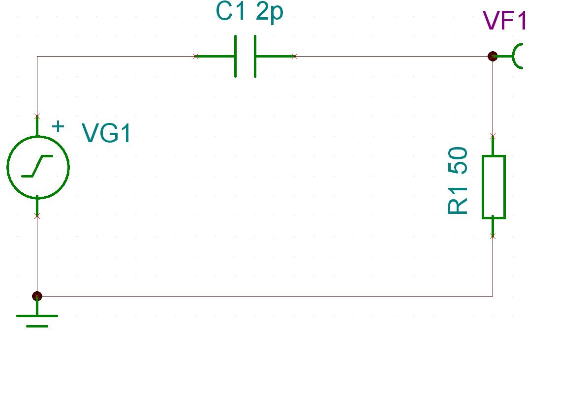
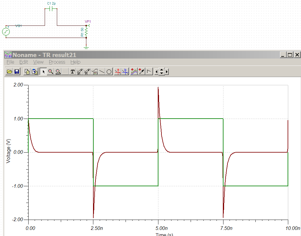
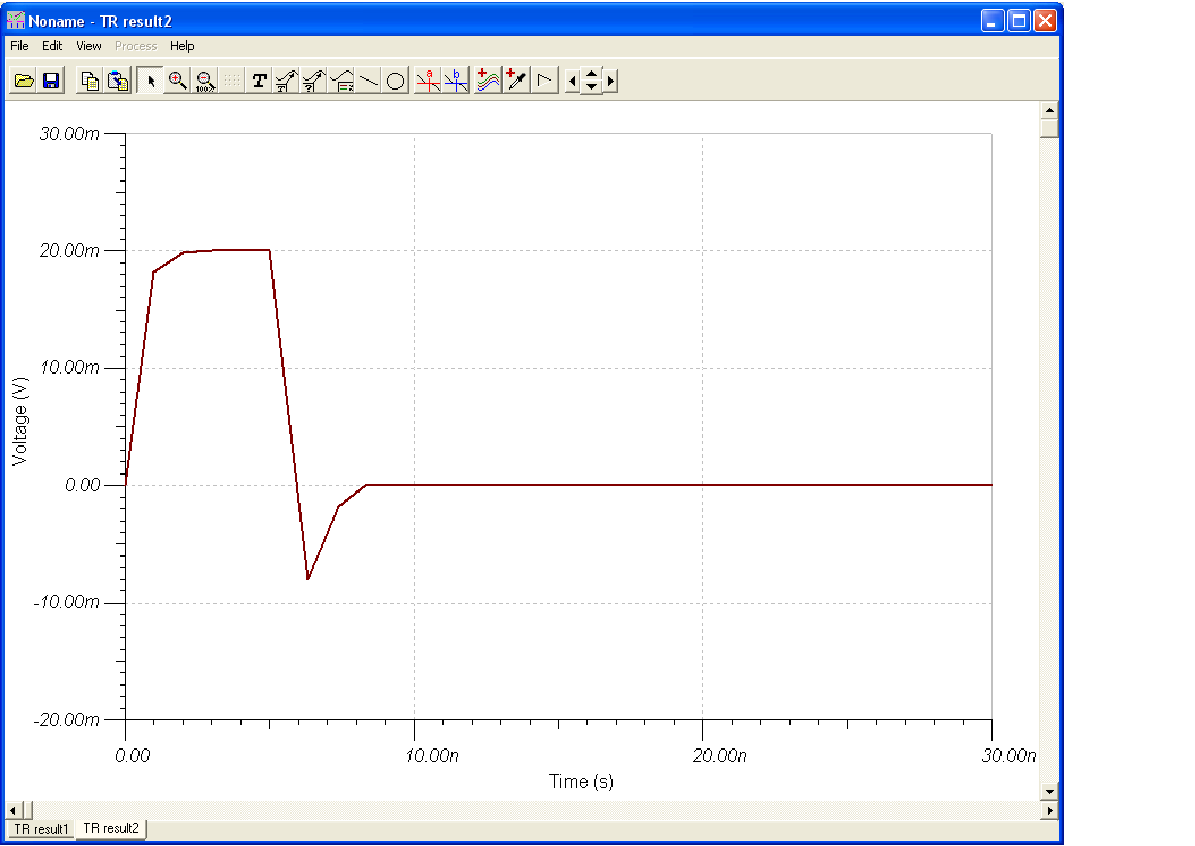
C=2pF, R=50ohms, Vs is a square wave with f=1MHz, Tr=Tf=5ns, A=1V. 

The simulation result shows the voltage across R is 

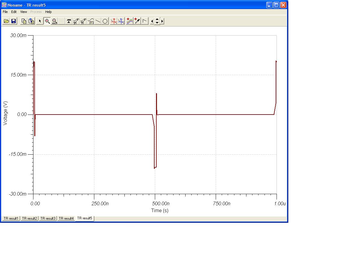
Can anybody tell me where the undershoots come from? Thanks.

Regards

xiao

  • Xiao,

            The circuit you provided is a high pass filter with a cutoff frequency (fc) of 1/(2*pi*R*C) which in this case = 1.59 GHz, thus any signal below fc will be attenuated. However remember that for a capacitor the transient current equals i(t) = CdV/dt thus if the voltage changes quickly i.e. dt is small, a large instantaneous current will be generated that. This current will  produce a spike when it flows through resistor R1 to generate the output voltage VF1. Basically the over/undershoot you are observing is due to the charge injection and charge distribution that is happening as the square wave cycles through the circuit. I hope this answers your question. 

    Regards,

    Marcos.

  • Xiao,

    I assume you are looking for the step response of a first-order system. Please note that the circuit has a time contant of 100ps, and the rise/fall time of the input is 5ns. So the circuit is fast enough to follow the input, hence you don't see VF1 to ever reach the input levels (the first tip should be at 1 V and the subsequent tips should be at +/-2 V).

    In addition, you are looking at a 100ps circuit in a 1us window, the wavefrom doesn't have enough resolution during the transitions.

    Please make your input much faster than the circuit by reducing the rise/fall time of VG1 to well below 100ps and rerun the simulation. I would also suggest you use a smaller time window so there will be enough resolution (which means you may want to increase the singal frequency to see more transitions). For example, the following waveform was obtained with VG1 at 200MHz and 1ps rise/fall:


    Alternatively, you can increase the time constant to well above the rise/fall time of the input signal by increasing the values of either the resistor or the capacitor.

  • Xiao,

    I think to certain extent, your question is not 100% clear. Are you referring to the overshoot/undershoot because of the natural CR response?

    or are you referring to undershoot ONLY that happens for instance around 0uS from 0 to -7.5mV?

    Around 0uS there are three spikes, the one from 0 to +20mV, then +20mV to 0V and then from 0V to -7.5mV.

    The CR response as explained by Marcos and JC will produce the 0 to +20mV, then +20mV to 0v. This is due to natural CR response combined

    with slow slope of the voltage generator.

    However, if you're referring the one from 0 to -7.5mV, I think that is the artificial effect of the simulator depending on your maximum time step.

    Assuming you use default value for most of the tolerances SET ANALYSIS PARAMTERS, I was able to see the 0 to -7.5mV kind of spike, we

    can eliminate this easily by changing the TR Maximum Time Step from 10G to 100p for instance. This should eliminate that spike.

    Herman

  • Hi Marcos,

    Thank you for your explanation. I know the spike is caused by the rapid change of voltage at the rising and falling edge of the square input. But if we zoom in the spike, we can see there is a undershoot during the decrease of the spike. I thought it should be an exponential decrease due to the decrease of the transient current. I don't know why there is an undershoot during the decreasing of the spike. Can you please help me with this?

    Regards

    Xiao

  • Hi J.C. Zhu,

    I'm sorry I didn't  describe my question quite clearly. Actually, I want to see the ramp response of RC circuit when the time constant is much smaller than the rising time of ramp input.(In my circuit, 5ns>>100ps) As you said, the VF1 should increase to a value which is much smaller than input level. Then it will decrease to zero exponentially due to the reduce of current. But I really don't know where the undershoot comes from. 

    Regards

    Xiao

  • Hi Herman,

    Your answer really helped me. I know now why the spike (from 0 to -7.5mV) appears. Thank you very much.

    Regards

    Xiao