

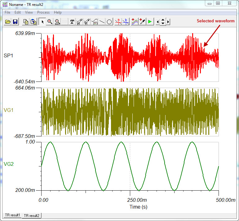
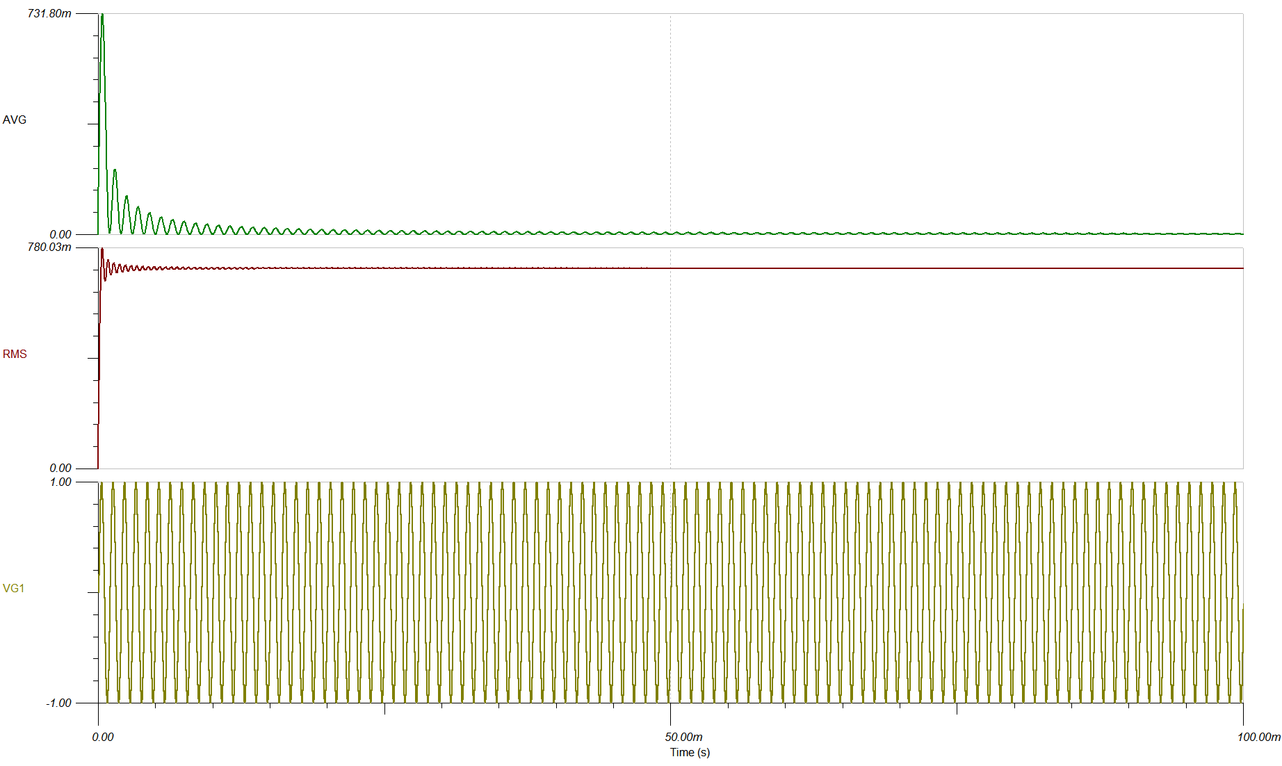
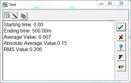
I want calculate an average value and effective value and plot them on the picture, how to edit the formula about the average value and effective value with the post-processor tools? thank you for your help.

-
Ask a related question
What is a related question?A related question is a question created from another question. When the related question is created, it will be automatically linked to the original question.


