This thread has been locked.

If you have a related question, please click the "Ask a related question" button in the top right corner. The newly created question will be automatically linked to this question.

Simulation of this circuit

2677.CPRDC.TSC

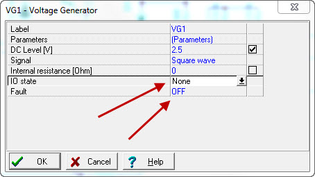
Hello Everyone, please find the attached simulation model of charge pump relay drive circuit, i have tried to simulate this circuit on TINA but nothing happen, i guess there is something wrong in the parameter selection or something else, i dont know, what i am missing specifically.


  • Samir,

    I get a ERC error for the RL1 SPNC-Defauly relay at the far right of the schematic. What is it's purpose? Is there a load after the relay that is missing? Also, the VG1 input has a DC level of 2.5V and then an 800Hz square wave of 2.5V. Is that the correct input? Make sure to have the IO state as Input and the Fault set to None on VG1.

    Are you running a transient simulation? When I run a transient simulation, it is set for 1us which won't show you much on an 800Hz waveform. You have not placed any voltage/current monitors either. Have you tried looking at any nodes in particular? What kind of output are you expecting?

    Not quite sure where to start with this particular circuit without a lot more information.

    Britt

  • Britt,

    Yes there is a load which is going to connect practically in final product, but here for the simulation its not require (we have a concern with the relay coil voltage).

    Idea of this circuit is to operate the relay by the charge pump relay drive concept, 5V DC clock signal (square wave from 600Hz to 10KHz) i am applying to this circuit, capacitor charge and discharge and turn the relay on, when i am stop applying clock signal from my microcontroller relay should stay open (means normally connect position), thats the summery behind the idea of this circuit.

    I have test this circuit on other simulator it is working well but in TINA its not working, i am not sure why? may be i am missing something which i dont know as i am new user of TINA.

    The purpose of choosing this TINA simulator is to check the practical reading, its more powerful tool compare to my traditional simulator.

    I want to run this circuit on TINA so i can figure out the drawback and modify my circuit according to that.

    I am doing simulation by Analysis-DC Analysis-calculate nodal voltage

    Thanks,

    Samir 

  • Hello Guys, please help me to solve above issue.

  • Samir,

    Did you make the changes I highlighted in the original post to VG1? If you did, you would notice that the curcuit does provide the DC information. Also, be sure to close the switch SPST1.

    From your circuit:


    Please change the fields to Input and None respectively and VG1 will work correctly. Not sure why these were changed from the default values.

    If you are only interested in the voltage provided to the relay, why is the relay necessary? You will continue to get the ERC warnings unless you remove the relay or add a load to it. Also, be sure that the Switch at the input is closed.

    Britt