This thread has been locked.

If you have a related question, please click the "Ask a related question" button in the top right corner. The newly created question will be automatically linked to this question.

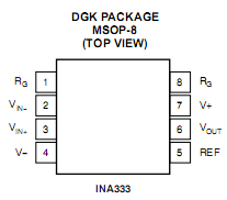
INA333 Tina-TI model input terminals are wrong.

Other Parts Discussed in Thread: TINA-TI, INA333

The + and - terminals of the stock Tina-TI part appear to be reversed.

The spice model is also incorrect (hence, two wrongs to make a right, for the simulation at least). If you are using the INA333 model provided by TI make be sure to correct the following section of the model:

Was:

*PINOUT ORDER RG+ VIN+ VIN- V- REF VOUT V+ RG-
*PINOUT ORDER  1   2    3   4   5    6  7   8
.SUBCKT INA333 1 2 3 4 5 6 7 8

Corrected:

*PINOUT ORDER RG+ VIN+ VIN- V- REF VOUT V+ RG-
*PINOUT ORDER  1   3    2   4   5    6  7   8
.SUBCKT INA333 1 3 2 4 5 6 7 8

Frank
Smart Electronics Corp.

  • Hello Frank,

    Thanks for pointing this out.  I will move the post to our Simulation and Models forum.

  • Frank,

    Actually, if that is the update you made without changing the node connections in the netlist, you have now changed the part performance by swapping the +/- Inputs. Run a quick simulation to see if you really get an inverting input now.

    The mapping of the subcircuit pins is tied the the netlist of the subcircuit, not to the symbol drawing in the datasheet. To actually correct this, you will have to change all of the node 2's to node 3's and vice versa in the netlist of the model netlist below. Be very careful in doing this because if you miss one instance, your model will not work correctly.

    Britt