This thread has been locked.

If you have a related question, please click the "Ask a related question" button in the top right corner. The newly created question will be automatically linked to this question.

Using Tina-Ti Fourier Series analysis

Other Parts Discussed in Thread: TINA-TI, TL081

Hello

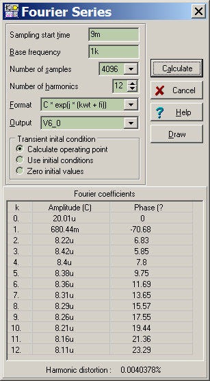
I have Tina-Ti, with all types of analogs circuits simulations, wen I use the Fourier Series analysis it give wrong values since it give mostly between 7% and 50% of distortions reading, I did compared those distortions numbers of my circuits by making prototypes using my HP distortion analyser and the number are a allways under .01% of distortion with my HP.

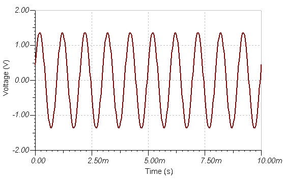
I include an image of test circuit on Tina-Ti.

Do I made any errors in my use of the Fourier Series ?

A helps are welcome.

Thank you

Bye

Gaetan


  • Hi Gaetan,

    Can you plot the transient waveform on VF2? If it resembles a sine wave then the problem is in the settings for the Fourier Series.

    Thanks,
    JC

  • Gaetan,

    By the way, try not to start the sampling at time=0, as the output usually need a few cycles to enter pseudo-steady state. Instead, only sample the last period. You may also want to tight up the tolerance in analysis parameters. Note that 16384 samples in one period will only give you up to the 14th harmonic.

    Regards,

    JC

  • Hello

    I did start the sampling of the Fourier series at time=1 and it was still giving the same erronous high distortion reading.

    I did the steady state analysis in transient method, you can see the sine result in the image I Include here.

    Thank

    Bye

    Gaetan


  • Gaetan,

    The waveform doesn't look close to a nice sine wave. Can you post your TINA design (.TSC) here?

    Thanks,
    JC

  • Hello

    The forum editor software refuse to upload the TINA design (.TSC)file, so here is Netlist .

    Thank

    Bye

    Gaetan


    TL081 TEST (TINA Netlist Editor format)
    ********************************************
    **  This file was created by TINA        **
    **    (c) 1996-2006 DesignSoft, Inc.   **
    ********************************************
    .LIB "<TINADIR>\EXAMPLES\SPICE\TSPICE.LIB"
    .LIB "<TINADIR>\SPICELIB\Operational Amplifiers.LIB"
    .TEMP 27
    .AC DEC 33 10K 10MEG
    .TRAN 20N 10U
    .DC LIN VG1 -7.5 7.5 150M

    .OPTIONS ABSTOL=1U ITL1=100
    .PROBE V(6)

    V2          0 2  15
    V1          1 0  15
    VG1         5 0 DC 0 AC 1 0
    + SIN( 0 1 1K 0 0 0 )
    C3          0 1  10N IC=0
    C2          2 0  10N IC=0
    C1          3 4  10N IC=0
    XU1          5 4 1 2 6   TL081_0
    R1          0 6  1K
    R3          4 6  10K
    R2          0 3  10K


    .LIB "<TINADIR>\SPICELIB\Operational Amplifiers.LIB"
    * TL081 OPERATIONAL AMPLIFIER "MACROMODEL" SUBCIRCUIT
    * CREATED USING PARTS RELEASE 4.01 ON 06/16/89 AT 13:08
    * (REV N/A)      SUPPLY VOLTAGE: +/-15V
    * ------------------------------------------------------------------------
    *|(C) COPYRIGHT TEXAS INSTRUMENTS INCORPORATED 2007. ALL RIGHTS RESERVED. |
    *|                                                                        |
    *|THIS MODEL IS DESIGNED AS AN AID FOR CUSTOMERS OF TEXAS INSTRUMENTS.    |
    *|NO WARRANTIES, EITHER EXPRESSED OR IMPLIED, WITH RESPECT TO THIS MODEL  |
    *|OR ITS FITNESS FOR A PARTICULAR PURPOSE IS CLAIMED BY TEXAS INSTRUMENTS |
    *|OR THE AUTHOR.  THE MODEL IS LICENSED SOLELY ON AN "AS IS" BASIS.  THE  |
    *|ENTIRE RISK AS TO ITS QUALITY AND PERFORMANCE IS WITH THE CUSTOMER.     |
    * ------------------------------------------------------------------------
    * CONNECTIONS:   NON-INVERTING INPUT
    *                | INVERTING INPUT
    *                | | POSITIVE POWER SUPPLY
    *                | | | NEGATIVE POWER SUPPLY
    *                | | | | OUTPUT
    *                | | | | |
    .SUBCKT TL081_0     1 2 3 4 5
    *
    C1   11 12 3.498E-12
    C2    6  7 15.00E-12
    DC    5 53 DX
    DE   54  5 DX
    DLP  90 91 DX
    DLN  92 90 DX
    DP    4  3 DX
    EGND 99  0 POLY(2) (3,0) (4,0) 0 .5 .5
    FB    7 99 POLY(5) VB VC VE VLP VLN 0 4.715E6 -5E6 5E6 5E6 -5E6
    GA    6  0 11 12 282.8E-6
    GCM   0  6 10 99 8.942E-9
    ISS   3 10 DC 195.0E-6
    HLIM 90  0 VLIM 1K
    J1   11  2 10 JX
    J2   12  1 10 JX
    R2    6  9 100.0E3
    RD1   4 11 3.536E3
    RD2   4 12 3.536E3
    RO1   8  5 150
    RO2   7 99 150
    RP    3  4 2.143E3
    RSS  10 99 1.026E6
    VB    9  0 DC 0
    VC    3 53 DC 2.200
    VE   54  4 DC 2.200
    VLIM  7  8 DC 0
    VLP  91  0 DC 25
    VLN   0 92 DC 25
    .MODEL DX D(IS=800.0E-18)
    .MODEL JX PJF(IS=15.00E-12 BETA=270.1E-6 VTO=-1)
    .ENDS


    .END

  • Gaetan,

    Thanks for the netlist. I ran a transient for 10ms. As the input frequency is 1KHz, I simply took the last period (from 9ms to 10ms) and calculated the Fourier series on that, which gave me < 0.005% THD on net 6 (where you have VF2 in the schematic. This is with 4096 samples in 1 period, or 12 harmonics:

  • Hello

    My error was that I've use the wrong sampling start time.

    I will use 10ms now on.

    That you

    Bye

    Gaetan