Because of the holidays, TI E2E™ design support forum responses will be delayed from Dec. 25 through Jan. 2. Thank you for your patience.

This thread has been locked.

If you have a related question, please click the "Ask a related question" button in the top right corner. The newly created question will be automatically linked to this question.

Demodulation of a FM-Signal with a PLL

Other Parts Discussed in Thread: TINA-TI

Hey,

I hope you can help me. I try to demodulate a FM-Signal with a self made PLL. I want to use the Analog System Lab Kit Pro do it. But I have already a problem with the simulation of it. The FM-Signal is made by a VCO. The same VCO is build in the PLL. I don't know where the problem is. I can't imagine that the loop-filter or the VCO is the failure but I can't simulate it. I tried to use other Filters and also other periphery for the op amps but it dosen't work.

I upload the TINA-TI file at the end of the post.

I hope somebody can help me.

Best regards

Martin

7416.PLL2_ASLK.TSC

  • Hi Martin,

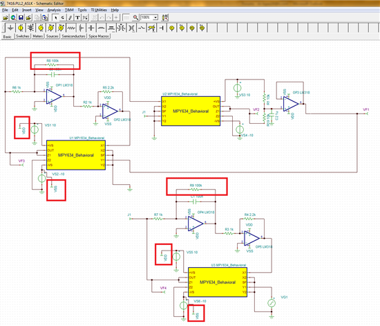
            I've made a few changes to your schematic to get it to run. First thing I noticed was that source VS2 and VS6 where shorted together by using a pin with the same name VSS the same thing applies for VDD see attached figure. Shorting two dc sources will give you the "current of component xx" error so that error is gone. Another little change I made was to add resistors R8 and R9 in parallel with the integrator caps C3 and C1 respectively to help with the convergence. I have attached a new schematic withe the aforementioned changes. Please feel free to post any  questions or concerns.

    Regards,

    Marcos

    7416.PLL2_ASLK.TSC