This thread has been locked.

If you have a related question, please click the "Ask a related question" button in the top right corner. The newly created question will be automatically linked to this question.

Webench unable to find device message

Guru 56218 points

Other Parts Discussed in Thread: LM5122, LM5112

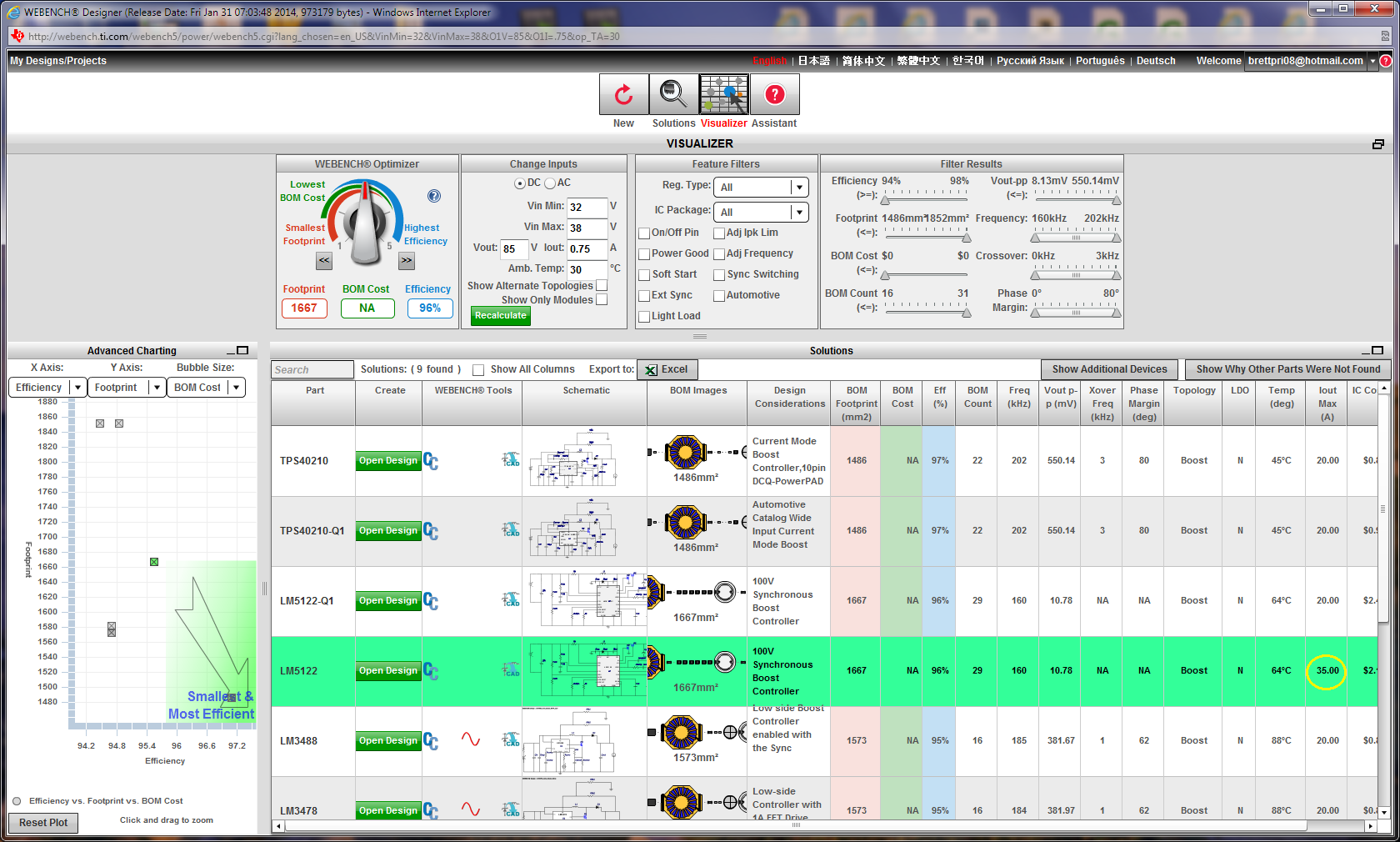
Wbench device builds a BOM for LM5122 rated at 35 amps max current and has alternate BOM selection to include several FETS rated up to 50 amps.

The issue is the input current for switcher FET M1, M2  appears to be restricted by the initial user input current and the schematic never shows the newly selected or updated higher amperage device in the BOM, updated for M2 and only M1 is actually being updated.  

The highest available inductor L current rated 3.4 amps selected as an alternate in BOM is actually under rated for the LM5122 maximum current handling capability of 35 amps being listed. That appears to be hindering the M2 device maximum current selection.

A work around could allow a user supplied entry for the inductors characteristics in a benign Inductor part number called (custom inductor).


  • Hey Brett,

    Looking at the screen shoot, the design wasn't created. Can you please provide your design criteria and let me check why the design failed to create. Most likely, the design may not be able to find the suitable components to meet the input conditions. 

    BTW, how did you get the inductor current rating if the design was created?


  • Hi Howard,

    Now seeing M2 is tied to M1 in BOM no mater if user first select M2 the FET Amps value is always lower. The yellow circle in picture leaves one to believe high switching currents are achievable using Designer. Power Stage Designer Tool 2.1 list 10.69uH choke for 6.5 amps load and switching frequency jumps upward 385-500Khz giving a minimal ripple current however frequency beyond LM5122 capability. Willing to use other IC if the frequency becomes the dynamic allowing instantaneous current demand. So far a linear power approach is winning the game.

    Webench Designer has no dynamic current tolerance value which ends up diverging the results for any anticipated load or efficiency standard predicated upon usage and demand.

    Primarily my issue is being able to designing around components able to withstand the instantaneous turn on load current projected to be roughly 85 volts 5.2 amps for 500ms-1sec without tripping the switcher into current limiting or seeing smoke. The average running load current well under that typically 1-2 amps could go even higher for longer periods of time. BLDC motors have large current demand to get rotor moving and current varies with actual rotor load.

    Entering a lower expected load current gets the user in the designer door.


  • Hey Brett,

    Thank you for the detail information on the design requirement but knowing the details, the LM5122 single IC won't be able to support your design because you have to design for the worst case. Your input design should be: 32V-38Vin, 85Vout, and 5.2A Iout. Of course, WEBENCH wasn't able to create the design because it could not find the FETs in our database to support the design.

    However, the LM5122 supports Dual Phase Interleaved Boost Configuration which will work for your requirement. If you can send me your direct contact information, I can direct you to the product application engineer who can help you.

    howard.chen@ti.com


  • WEBENCH wasn't able to create the design because it could not find the FETs in our database to support the design.

    You mean an unbreakable preconfigured pair M1M2 each of same amperage. Oddly any of the alternate BOM selections were not matched in amperage, M1 was always a higher amperage than M2.

    Watching the LM5112 video,  Eric shows master slave mode but leaves out what the benefit doing so would be. Assuming Slaving another LM5112 would some how double current, WEBENCH not able to use Slave configuration to show me the benefit of adding One or multiple Slaves. Not to fret the datasheet left me equally bewildered as to what benefit and why daisy chain slaves of synchronous PCB's singing the "Night Old Dixie Died." :)


  • Hey Brett,

    For the base design, WEBENCH optimizes the BOM list for cost and efficiency which means using a pair FETs can support the highest current rating of the design.

    In the alternate component feature, it becomes a bit more custom so there are still chance you can find pairing of the FETs.

    You question of why M1 has higher current rating than M2 is detected by the duty cycle of the design and that resulted a higher current is seen by M1.

    At the moment, WEBENCH does not support muti-phase designs. I have stated that I will get you in contact with Eric directly and maybe he can help you.