This thread has been locked.
If you have a related question, please click the "Ask a related question" button in the top right corner. The newly created question will be automatically linked to this question.
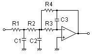
hello, everyone. I need to calculate the filter circuit like this(first passive stage R1/C1+second active MFB):
http://sim.okawa-denshi.jp/en/MultipleFB3Lowkeisan.htm
The link above, I can get the circuit, but I can not change the values of resistors and capacitors for my needs.
Maybe there is a program which allows to consider such a scheme and to change the values of resistors and capacitors?
Or it may be the formula for the calculation of the manual?
Vitalij,
I would like to suggest that you look at TI's WEBENCH Filter Designer. This tool will help you define all of your Rs and Cs for any order flter. You will notice on page 3 of this software, you can change from Sallen-key to MFB circuits.
Vitalij,
Actually this filter is realized with a standalone first order filter followed by a second order. A lowpass, 3rd order, Butterworth, cut-off frequency 1 kHz, MFB circuit looks like this:
The reason that your starting R/C pair is replaced with a 1st order amplifier lowpass circuit is because we found there was interaction between the elements with your circuit. This interaction did not provide the response that you would expect, ie somewhat imperfect.
This scheme has a specific transfer function, and certain Damping ratio = ~ 0.73(for bessel).
For me, this is the solution, and I will not use 2 pcs. operational amplifiers.
Yes, I can see your point. Filter Designer does have the ability to design Low Pass Bessel, but the third order always does have two amplifiers.
As you go about selecting your amplifier for your filter be careful of the Q of the filter, bandwidth of the amplifier, input bias current, and slew rate of the amplifier. Here are some guidelines for these issues:
Vitalij,
I thought that I gave you good links but for some reason it is not working. Here are the links in order.
good luck.