This thread has been locked.

If you have a related question, please click the "Ask a related question" button in the top right corner. The newly created question will be automatically linked to this question.

Webench .TRAN parameters and 8 minute time limit

Other Parts Discussed in Thread: TPS54478, TINA-TI, TPS56121

I am simulating TPS54478 successfully with default settings which have TSTOP=1.2ms. But my device needs to be simulated to 50ms and if I try to do that I get the error message "SIMULATION TIME LIMIT WAS EXCEEDED". .TRAN parameters TRES, TMAX and KCLTOL are default 10ns, I try changing them all to 100ns but get the same error. And more than ~100ns I shouldn't use since fsw is 1MHz.

I also wonder what TSTEP and KCLTOL do, I don't think they are standard SPICE directives.

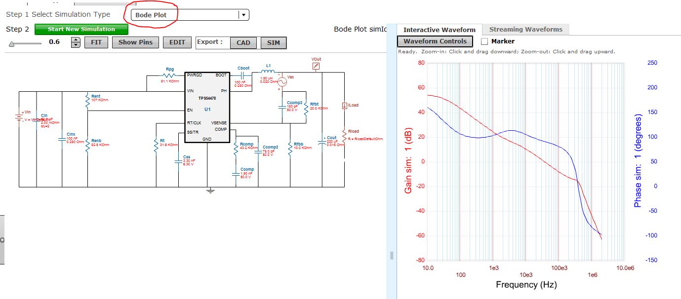
My goal is to select preliminary values for compensation link so that my hardware won't oscillate, which would give me a good starting point when measuring and adjusting the loop in the lab. I was planning just to look at oscillations during startup. Even better would be to see Bode plots but I don't think that can be done?

It plots a graph (slowly) during the 8 minutes so it doesn't seem to diverge, just being slow.

  • David,

    The TPS54478 does have Bode Plot support for simulation in WEBENCH®. It is under the simulation window pulldown:


    The simulations are limited to 8 minutes or less for socket timeouts in the internet protocals. If you need to actually run a simulation for 50ms, the best option would be to export your design to TINA-TI and run the simulation locally. You cna then adjust any of the parameters that you need to adjust.

    The actual clock time for this length of simulation would probably be on the order of a couple of hours.


  • Thanks, the Bode plot would be nice but I don't have that drop down list. When i press the "Sim" button I get this:

    Tried both Firefox and IE. Costs extra?! :-/

  • David,

    The picture did not come through. No charge at all for the full features of WEBENCH®!

    Did you edit the schematic using the Schematic Editor? If so, the only simulation available would be a startup simulation.

    If you did not need to change the topology of the circuit, you do not need to use the Schematic Editor. You can change component values via the BOM or schematc by simply clicking on the component and choosing an alternate component.

    If you did have to change the topology, you should still be able to export the design to TINA-TI.

    You can also access the Bode Plot through the Charts button if you have not used the Schematic Editor. These charts and OpVals are updated when you change component values without having to run a simulation.


  • Oops apparently the editor can't handle pasting a picture even though it looked ok when editing. Here it is, uploaded:


    I also tried opening the original TPS54478 webench design and there I do have a drop down menu with Bode as a choice. Strange, all my edits were plain passive components from your lists. Also a bit strange that I have the tab "Parameters" (with .TRAN parameters) but no such tab in original design.

  • Oh. Bummer. I need to change the schematic, we have e g type III compensation (and I couldn't find a way to change "QTY" so I had to add capacitors). So I can't use Webench then? Can I get Bode plots in Tina-TI?

  • David,

    You used the Schematic Editor for your edits. If you click on the Edit button as shown in the previous post, you will get a window to ask to create a copy of the design before proceeding. If you click OK, the Schematic Editor is invoked and you design will show the Custom Design tag (in your picture, upper left corner). This takes you into the full simulator interface where you can change the topology of the circuit, add passive and active components and do some interesting manipulations as you would in a full simulator.

    If you only want to change the values of components, start from the original design from the product folder where you input your conditions. Once the design is created, go to the schematic page and right click on the component you wish to change and select an alternate component (or you can do this from the BOM page as I showed previously). Once a component is changes, the OpVals and charts are updated and you can see the impact quickly on your perfromance. Once all of the updates are made, you can then run the simulation (Bode Plot, etc.) to verify your changes.

    Both the Schematic Editor and WEBENCH® Power Designer use the same inteface for pasive component changes. If you do not use the Schematic Editor button, I believe you will be able to do want you want and see the results you were trying to obtain.


  • Well thanks but all in all that means I have no use for Webench: Can't have type II or III comp to get Bode plots, can't do transient analysis longer than 1-2ms, can't edit .TRAN parameters in a way that extends this time, and no explanation of the .TRAN TI specific parameters.

    I've managed to install Tina-Ti now and export the Webench designs there. If anyone reads this then let me tell you don't use the "File / Export This Design" button, nothing happens (it's in the Edit window i e where you get when opening a saved design), and don't press "CAD Export" because Tina-Ti can't import any of that AFAIKS. No, press "Sim Export" and select "Tina-TI" then Download. This you can open in Tina-TI. I read this in another thread in this forum.

    Now I'll be trying to get Tina-Ti to produce Bode plots.
  • David,

    There is a TINA-TI average reference design in the product folder that uses type 3 compensation. It can be found here:

    http://www.ti.com/product/TPS54478/toolssoftware

    Click on the Average Reference Design to download.


  • Thanks. I already tried importing the Webench design to Tina-TI and running it as-is (i e transient analysis) works. So I suppose I can at least run it for the required duration. A funny thing is that it doesn't use the normal source but a SUBCKT:

    Regarding the average model, are you saying my present design, imported from Webench, won't work in Tina-TI for Bode plots? A bit surprising since it works for Bode plots in Webench normally. Guess I'll find out if I try. Otherwise I'll use the average model.

  • David,

    For switching power supplies, you can not use the transient model to perform Bode Plots using standard spice techniques. This is due to the fact that you need to calculate the DC Bias point first to linearize the circuit for AC simulation. However since the circuit is switching, the DC Bias point can not be calculated by Spice. Hence we need a separate kind of model for AC simulations of switching power supplies. This is called an average model. In this model the switching nodes are averages out over a switching cycle so DC Bias point can be calculated. You can read up more about this in this FAQ.

    Thanks,

  • Thanks, I know about average models and their use for Pspice (I have Basso's 900 page book on the subject). But what I don't understand is why I can get Bode plots in Webench with this model but not in Tina-TI with the same model. I'm guessing Tina-Ti is Pspice-based, and that Webench is not, but still I wasn't aware you could use transient models for Bode plots. PSIM and LTspice use different techniques to overcome the drawbacks with Pspice for SMPS but I haven't tried them for it, I don't know if they can do this. Main problem with LTspice and TI I think is that you have encrypted the contents so that they don't work so no use trying that, right?
  • Edit: Webench also seems to be some SPICE version (but with TI specific parameters) since you have the -TRAN statement. Just a detail, I still don't understand why Webench can do what Tina-TI can't (provided I don't change the schematic). Seems the two ways forward I can try both are in Tina-TI: Either run a longer transient analysis with the imported schematic (provided I don't have to adjust the comp network, that would be hard, only good to verify that looks good enough), or redo the schematic with average model and get Bode plots.
  • Another peculiarity is that for TPS56121, "Bode plot" is missing in the dropdown menu even if I haven't changed any values.
  • Hi David,

    Currently Bode plot simulation is not enabled for TPS56121 inside WEBENCH. However you can look at the Bode plot from the "Charts" section in WEBENCH.

    Thanks,
  • David,

    To answer your other questions:

    1. In WEBENCH, since the model is not visible to the user, it might appear that it is using the same model for Bode plots and for transient simulations, but that is not the case. The models are unique for both type of simulations.

    2. Transient model can be used for Bode plots for non switching circuits. For switching circuits, the case is unique and required Average models (traditional approach). Some new simulators are coming up with unique techniques to generate Bode plot from transient models but many of these simulators are non spice based like PSIM.

    3. TI encrypts many model to protect the IP. However, recently we have started releasing many of the models unencrypted to the web. If you go to the link below (spicerack). and search for the word "unencrypted" in the search box, you will find all unencrypted models provided by TI for Power.

    4. Since WEBENCH is a web based tool, there is an inherent timeout associated with it so you can not run long simulations with it right now. If you do need to run long sims, exporting the design to a standalone simulator like TINA-TI is recommended.

    Your feedback is valuable so keep it coming. We will consider your suggestions for future development work.

    Thanks,
  • Thanks. Great that I can find the Bode diagram under Charts although I don't understand how you create it if not by simulating.

    I have a problem though: I am not allowed to add components to the schematic if I want to get a Bode plot they said, and I run TPS56121 at 1MHz so I have to add a 13.3k resistor. Bummer. Have to use Tina-Ti for everything it seems.
  • The Bode plot in the charts is from analytical formulation (not using spice). It is used to predict the stability of the circuit that is recommended by WEBENCH. In many cases, you may not find spice simulation models for Bode plots so we need the analytical formulation to predict the stability.
  • Ok thanks then I understand. But I guess that means your Bode diagram only supports fsw=500kHz i e i can not add the 13,3k resistor to the schematic which changes mode to fsw=1MHz and thus I must use Tina TI?

  • I can confirm that if I add 13.3kohms from COMP to GND (which is needed to change fsw from 500kHz to 1MHz) then only startup simulation is available and no charts. So Tina-TI it is. With the limited time I have this week I will export from Webench to Tina and run a transient analysis there with load step.
  • Oh Goodness (Utah equivalent to some very strong curse words)... The TPS56121 design I can not export in Tina format, since the Sim Export button doesn't exist, not even before I added my 13.3k resistor. I'm wasting a remarkable amount of time here on things that don't work. I recommend skipping Webench altogether and use only the less welcoming but more functional Tina-TI.
  • Hi David,

    Sorry for the inconvenience. We have recently introduced this feature called Sim Export and are in the process of enabling it for all the parts in WEBENCH. In order to see what features are enabled for what parts, you can refer to the following link

    http://webench.ti.com/webench5/devices/

    Also, if you go through the WEBENCH Panel from www.ti.com, you will come to the Visualizer Page which compares various solutions. There too all the features supported by each part are shown.

    Thanks,

  • David,

    Change of frequency can be achieved by changing the optimizer dial setting on the upper left corner. Typically Setting 3 is a balanced setting and will choose a middle frequency for the device (500KHz) in this case. If you want a higher frequency, you can adjust to Dial 1 (Lowest Footprint), if you want a lower frequency, adjust to Dial 5 (Highest Efficiency). In some cases, you may still see no change of frequency with Optimizer setting change since there are other design aspects to take into consideration like Min On Time violations, Min OFF Time Violations, Temperature rise (thermal shutdown), etc.

    Thanks,